
Heart model

a heart and model technology, applied in the field of anatomical modeling, can solve the problems of limited options, a large number and a final complex series of selectively displayed two-dimensional representations

Active Publication Date: 2005-06-16
MEDTRONIC INC
View PDF8 Cites 21 Cited by
  • Summary
  • Abstract
  • Description
  • Claims
  • Application Information

AI Technical Summary

Benefits of technology

[0015] The present invention also includes a method of making a heart model, comprising obtaining three dimensional data representative of a human heart. The method further includes fabricating a stereo lithographic rendering of the three dimensional data, generating a model from the rendering, removing a portion of the model, and replacing the removed portion with a low durometer material capable of receiving a helix of a cardiac lead.

Problems solved by technology

Computerized modeling allows for simulated three dimensional rendering; however, this is still ultimately a complex series of selectively displayed two dimensional representations.
True three dimensional modeling of cardiac anatomy is surprisingly sparse.
For many reasons, this is a very limited option.
These models provide a training aide that is useful for many applications, but does not provide a life-like approximation.
In many training or educational situations, these models fail to provide the appropriate environment or context.
Because of the unique environment and characteristics of lead implantation, the above noted cardiac models are insufficient in that they do not allow a practitioner to manipulate a lead in the same physical environment present in a living patient.
This configuration does not provide an accurate representation of the implantation environment.
The plastic tubing provides a frictional barrier and severely hinders and even precludes the advancement of a lead.
Any curvature of the tube increases this problem.
Thus, lead advancement cannot be accurately simulated.
The device also lacks any physical representation of anatomical structure within the heart and does not permit lead affixation.
This model provides a relatively accurate representation of the internal structure and topography of the heart, but leads can not be affixed to the stiff silicone, and visibility through the model is impaired.
Such models fail to provide for an accurate representation of the physical characteristics associated with lead implantation and affixation while still providing a meaningful teaching and training environment (e.g., allowing for appropriate visibility, lead insertion / advancement, affixation, etc.).
Likewise, once within a given heart chamber, there is complex topography and navigation issues (e.g., identifying and entering the coronary sinus, passing through a valve, identifying an affixation site, etc.).
Thus, the above models do not provide a comprehensive representative environment for simulating lead implantation and affixation.

Method used


Image

  • Heart model
  • Heart model
  • Heart model

Examples


Embodiment Construction

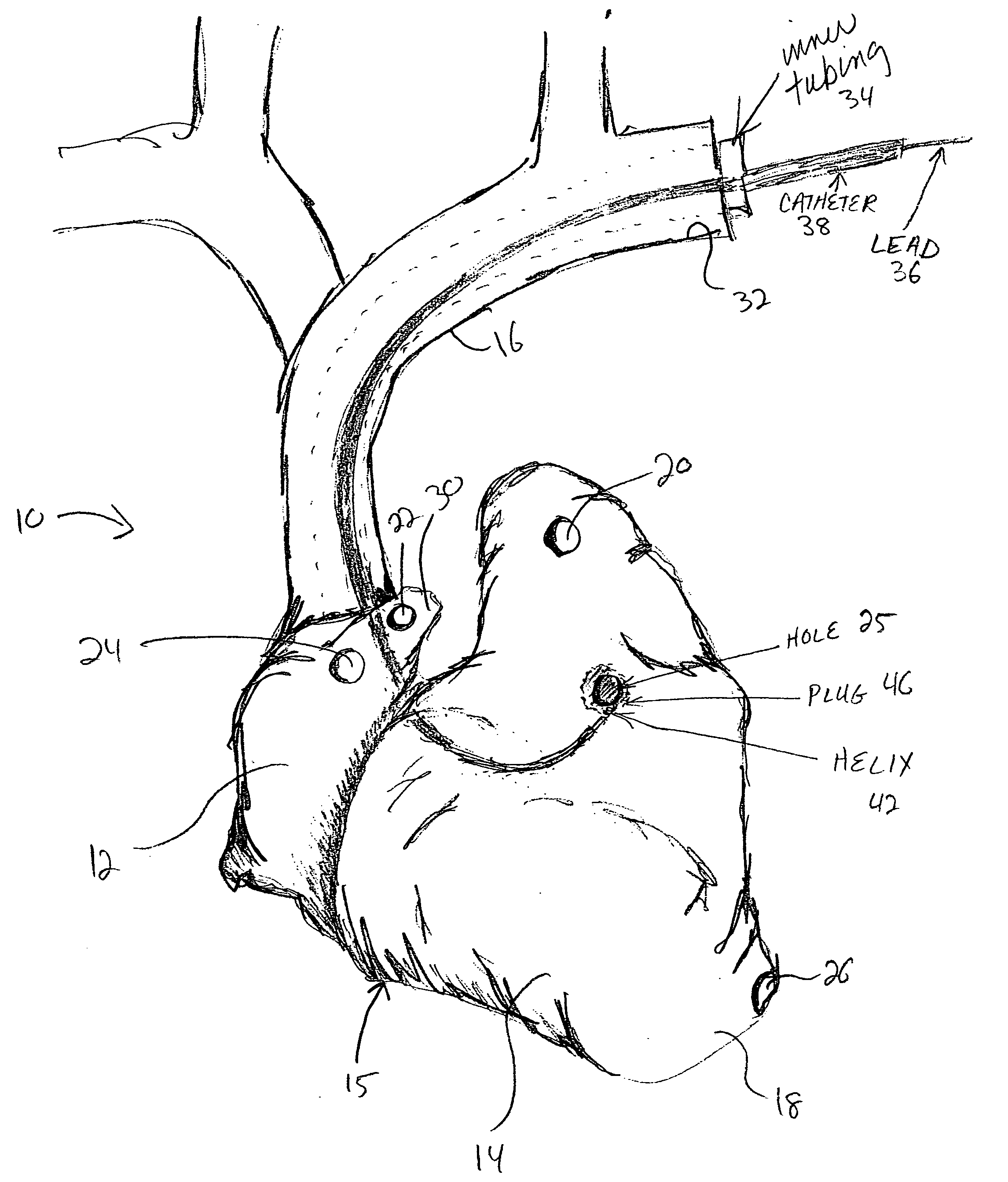
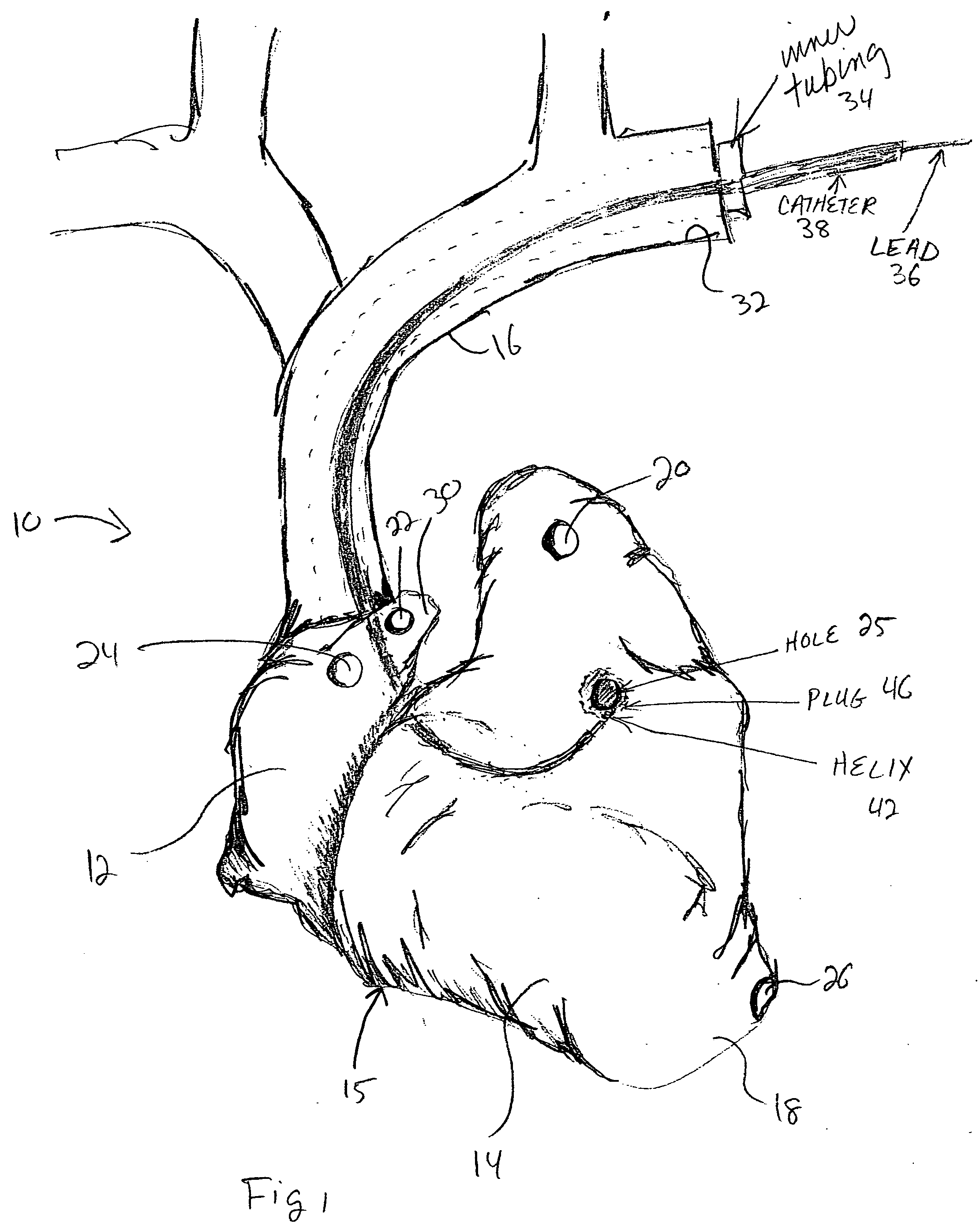
[0019] Referring to FIG. 1, a heart model 10 is illustrated, consistent with the principles of the present invention. Heart model 10 is a generally rigid structure that includes various anatomical cavities including a right atrial chamber 12 and right ventricular chamber 14. A portion of the venous anatomy includes a vein 16 representative of the superior vena cava. The vein 16 is generally rigid, having a passageway defined therethrough that is in communication with the right atrial chamber 12.

[0020] The extent of the cardiac anatomy and the accuracy of the heart model 10 can be varied depending upon the desired training, educational, or other intended purposed. For example, the entire heart including both atria and both ventricles may be included. Alternatively, only the left side of the heart, only the right side of the heart, or any portion thereof may be modeled, to reduce complexity for specific applications. In addition, any or all of the naturally occuring veins and arterie...


PUM


Abstract

A heart model provides a simulative environment for lead implantation and affixation. In one embodiment, removable silicone plugs are provided at appropriate locations so that an inserted lead can be affixed to the plugs with a helical tip. A simulative venous structure is provided that has increased lubricity to facilitate the insertion and manipulation of the lead.

Description

RELATED APPLICATION [0001] This application is related to, and claims the benefit of, provisionally-filed U.S. Patent Application Ser. No. 60 / 529,680, filed Dec. 15, 2003, and entitled “Heart Model”, which is incorporated herein by reference in its entirety.FIELD OF THE INVENTION [0002] The present invention relates to anatomical modeling. More specifically, the present invention relates to cardiac modeling. DESCRIPTION OF THE RELATED ART [0003] Basic human anatomy is relatively well understood. The anatomy of fundamental organs such as the heart and the cardiac venous / arterial structure (collectively cardiac anatomy) has been defined with a fair degree of precision for some time. Such an understanding is classically derived from dissection and direct observation of specimens, with the resultant data rendered in two-dimensional representations, such as drawings, sketches, or photographs. Newer technologies, such as MRI, CRT, PET, CAT and the like have provided tools for imaging card...

Claims


Application Information

Patent Timeline
Patent Type & Authority Applications(United States)
IPC IPC(8): G09B23/30
CPCG09B23/30B33Y80/00
Inventor ELLINGSON, ELIZABETH A.BOSER, GREGORY A.MILLER, DAVID L.LAHM, RYAN P.LAFAVOR, JILL A.RASMUSSEN, MANDY L.SHAH, SONAR
Owner MEDTRONIC INC
Learn More