
Remote video inspection system

a video inspection and remote technology, applied in the field of remote video inspection systems, can solve the problems of inconvenient and common size of the system, and achieve the effects of improving technical capabilities, improving convenience, and rapid set-up tim

Inactive Publication Date: 2005-06-16
GE INSPECTION TECH LP
View PDF98 Cites 158 Cited by
  • Summary
  • Abstract
  • Description
  • Claims
  • Application Information

AI Technical Summary

Benefits of technology

The invention is a modular remote visual inspection system that allows for quick and easy set-up and interchangeability between flexible probes. The system can be used for medical diagnosis or procedures, as well as for inspecting the interior of inanimate objects or equipment. The system includes a base module, interconnection module, display module, and control module, which work together to provide a view of a portion of an interior of an object of interest. The system can be easily transported and operational within 15 seconds of being carried to the inspection location. The invention offers improved convenience and technical capabilities for remote inspection.

Problems solved by technology

Such systems are commonly large and inconvenient to move to a remote site for inspection operations.
These systems, as described, have deficiencies in aspects such as portability and convenience that are general needs in the industry.

Method used


Image

  • Remote video inspection system
  • Remote video inspection system
  • Remote video inspection system

Examples


first embodiment

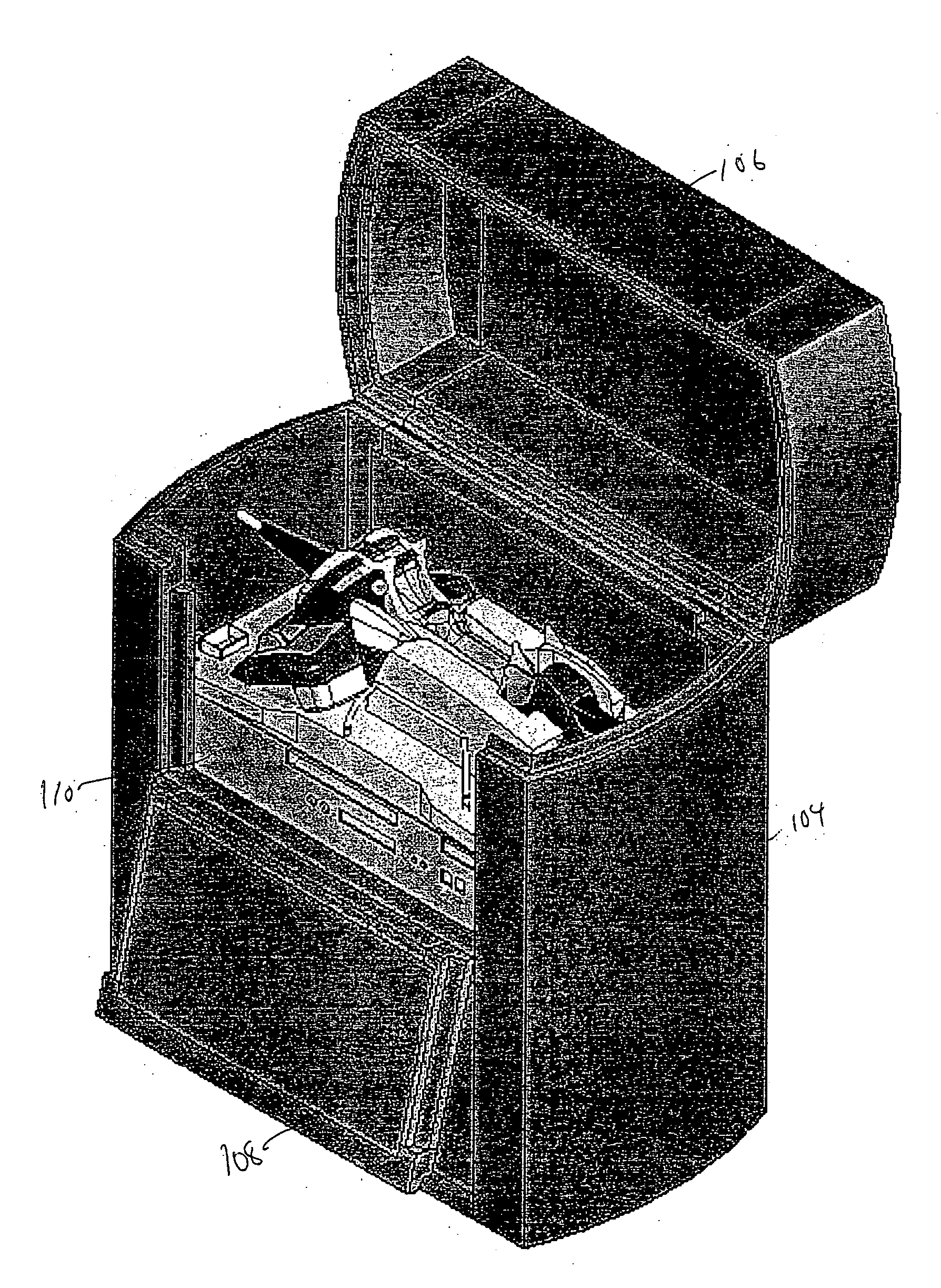
[0048] As shown at a high level in FIG. 1, the remote video inspection system 100 of the invention comprises a container module 102, such as a plastic case comprising a body 104 and a lid 106. Another embodiment of the remote video inspection system 100 of the invention is shown in FIGS. 5-23, which will be discussed further hereinbelow. FIG. 1 depicts the container module in an opened configuration, allowing the viewer to see some of the other components of the remote video inspection system (remote video inspection system 100) and their relation to the container module 102. As will be described in greater detail, the lid 106 in some embodiments is attached to the body 104 with friction hinges that can hold the lid 106 in any position, or a fixed number of set positions, such as a full open position, a workstation position, a rain shield position, and a closed position. In one embodiment, a handle locks the lid 106 in a workstation position. The lid 106 may have detents or one or m...

second embodiment

[0088] Referring to FIGS. 5-23, there is illustrated a remote video inspection system in accordance with the invention. In brief, the system herein also utilizes a case that includes a self-contained base unit that can be removed from the base, the base unit including a light source, battery, and a handset that is tethered to the portable hand-held base unit.

[0089]FIG. 5 illustrates features of a second embodiment showing the system in front view. The system comprises a container module 502 having a body 504 and lid 506 connected by hinges, with a base module 510 resting in a cavity defined in the body 504 of the container module 502. A pull out shelf 520 attached to the lid 506 has resting thereon a keyboard 530. The keyboard 530 is a keyboard such as is used with a conventional personal computer. The keyboard 530 can in different embodiments be a wireless keyboard, such as a keyboard that can communicate using infrared or electromagnetic waves, or a keyboard connected to the syste...


PUM


Abstract

A modular remote video inspection system for inspecting the interior of a living thing or of an inanimate object, such as a machine. The system comprises a base module connected by way of an interconnection module to a handset comprising a unitary display module and control module. The system makes observations by generating light that is caused to impinge on a surface of the interior of the object of interest. An inspection module attached to the handset comprises both a light guide for providing the light to the area of interest, and a selected one of a sensor and a light receiver. The inspection module comprises a steerable tip configured to be located adjacent the area of interest. The handset includes both controls for operating the system, and a display for providing a view of the region being inspected, as well as status information for the user of an operator.

Description

CROSS-REFERENCE TO RELATED APPLICATIONS [0001] This application claims priority to and the benefit of co-pending U.S. provisional patent application Ser. No. 60 / 443,521, filed Jan. 29, 2003, and of co-pending U.S. provisional patent application Ser. No. 60 / 520,996, filed Nov. 18, 2003, each of which applications is hereby incorporated by reference in its entirety.FIELD OF THE INVENTION [0002] This invention relates generally to remote video inspection systems, and in particular to a comprehensive remote inspection system that utilizes modular units, including a computation module, and that can communicate with a central computer workstation. BACKGROUND OF THE INVENTION [0003] Inspection units for remotely inspecting the interior portions of a body cavity of a living thing such as a person for medical diagnosis or a medical procedure, or for inspection or possibly repair of interior portions of industrial equipment, such as a boiler, a pipe or an engine, are known. Such systems are c...

Claims


Application Information

Patent Timeline
Patent Type & Authority Applications(United States)
IPC IPC(8): A61B1/005A61B1/05G02B23/24
CPCA61B1/00039A61B1/00041A61B1/00048A61B1/00052A61B1/00059A61B1/00105A61B1/0669A61B1/0051A61B1/05A61B2560/0431G02B23/24G02B23/2469A61B1/00108A61B1/0004A61B1/00042
Inventor BENDALL, CLARKBRITTON, TOMHUBBEN, EDWARD B.KARPEN, THOMAS W.LAMBDIN, THOMAS ELDREDLIA, RAYMOND A.SALVATI, JONSCOTT, JOSHUAVON FELTEN, KENABERNETHY, TODDOSIECKI, SCOTT
Owner GE INSPECTION TECH LP
Learn More