Multi-level DC bus inverter for providing sinusoidal and pwm electrical machine voltages
- Summary
- Abstract
- Description
- Claims
- Application Information
AI Technical Summary
Benefits of technology
Problems solved by technology
Method used
Image
Examples
Embodiment Construction
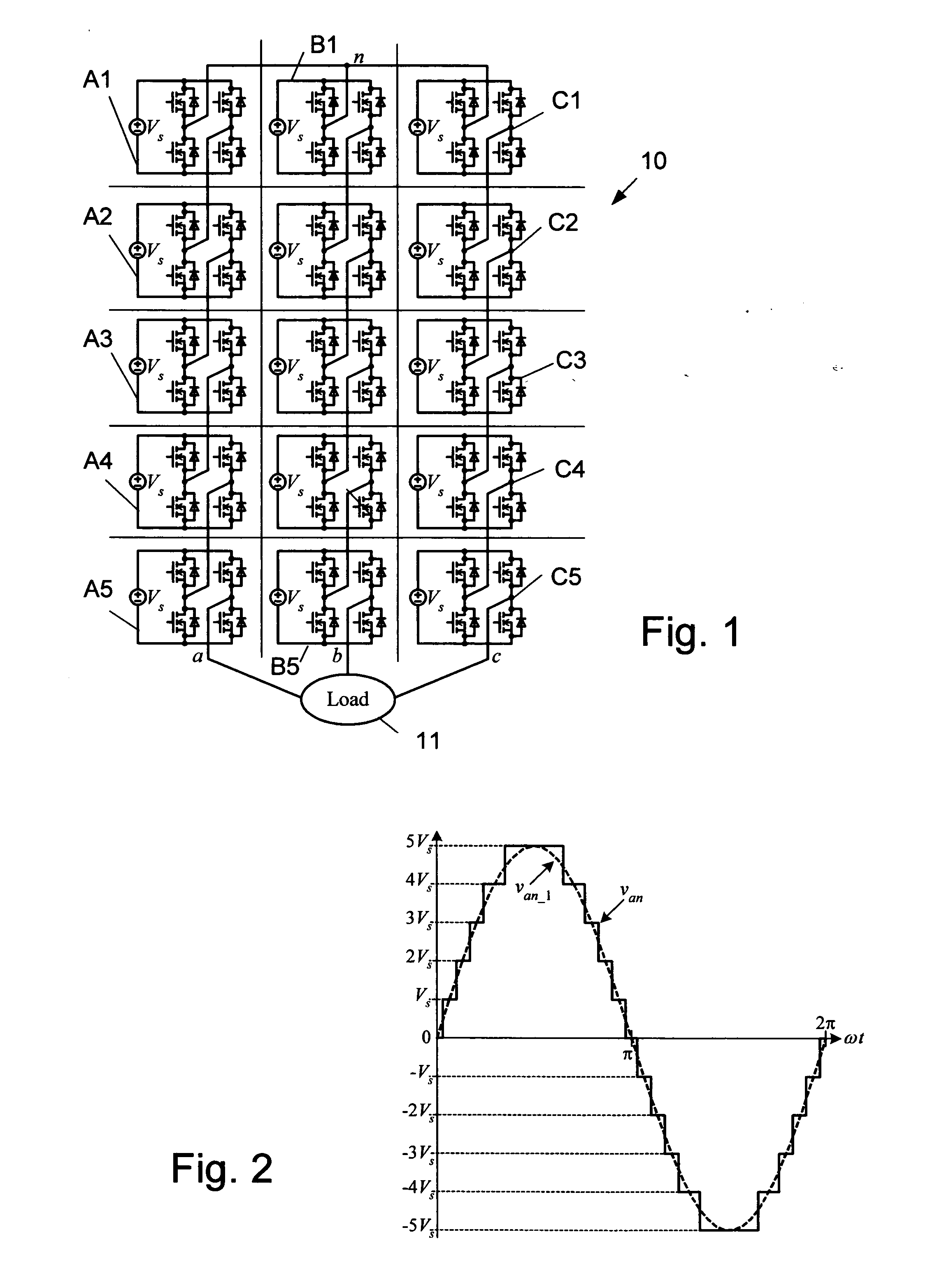
[0036]FIG. 1 shows the power circuit 10 for a three-phase, Y-connected cascaded H-bridge inverter with five cells A1-A5, B1-B5 and C1-C5 in each respective phase a, b and c for supplying a load 11. The phase voltage is synthesized by the addition of the voltages generated by each cell, which can have one of three values: —Vs, 0, or Vs. As seen in FIG. 2, the resulting phase voltage, van has a staircase shape of eleven levels, 5Vs, 4Vs, 3Vs, 2Vs, Vs, 0, —Vs, −2Vs, −3Vs, −4Vs, −5Vs, to approximate a sinusoidal voltage, van—1.
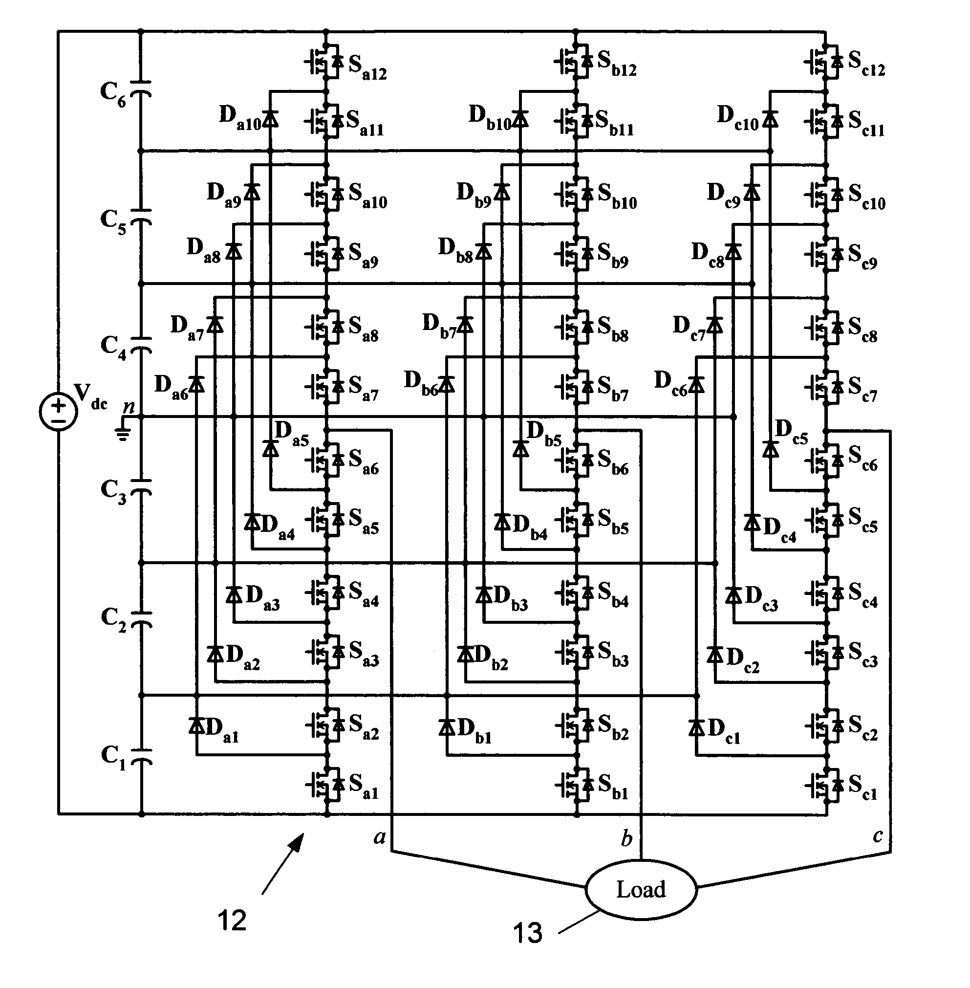
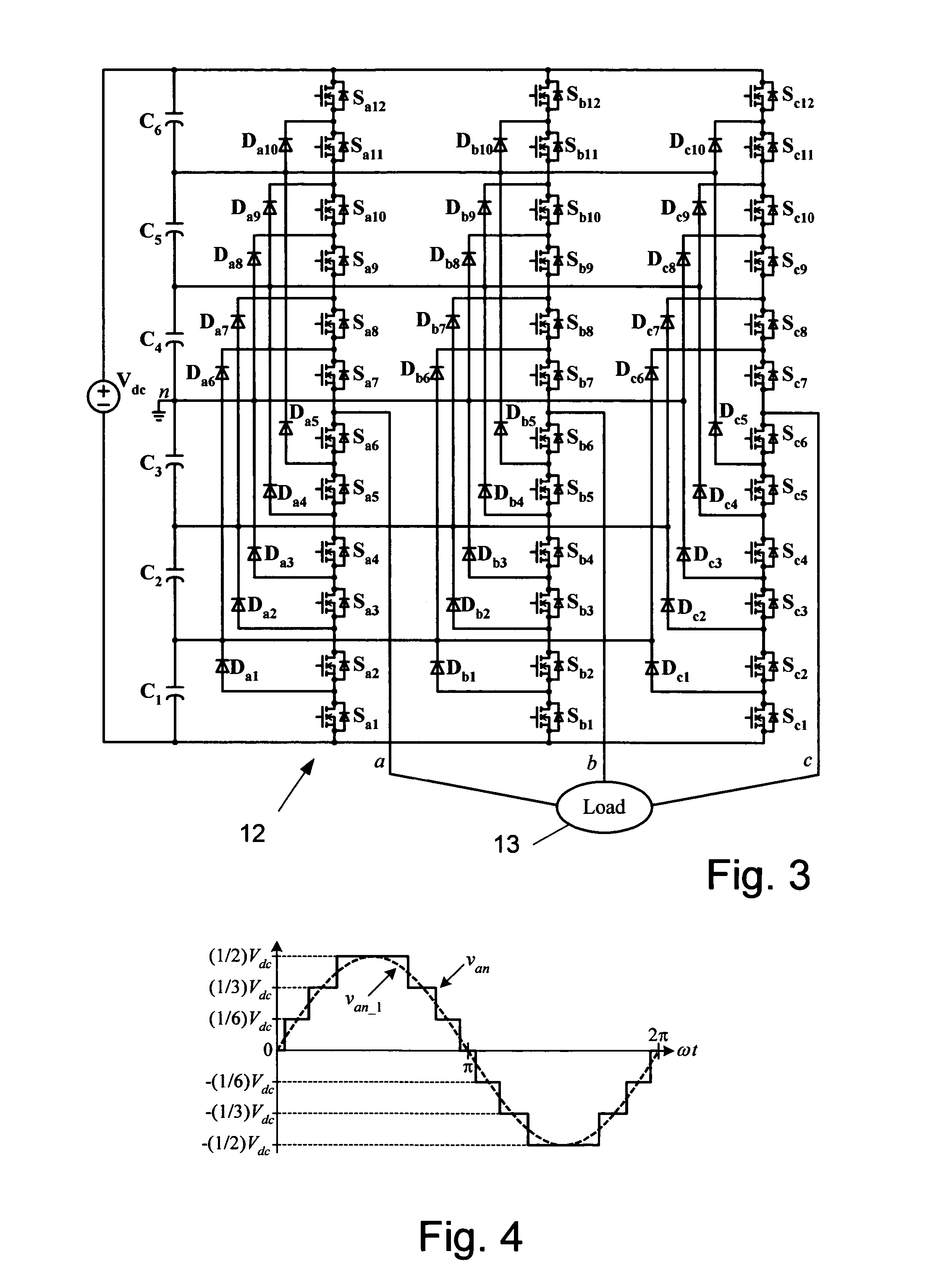
[0037]FIG. 3 illustrates a seven-level diode-clamped inverter 12 for supplying a load 13. In this circuit 12, the dc source voltage, Vdc is split into six levels by six series-connected capacitors, C1-C6. Defining the middle point of the capacitors n as the zero-reference point for the phase voltages and assuming the dc source voltage, Vdc is evenly divided by the capacitors, the inverter can produce staircase-shaped phase voltages of seven levels: Vdc / 2, Vdc / 3, ...
PUM
 Abstract
Description
Claims
Application Information
 - R&D
- Intellectual Property
- Life Sciences
- Materials
- Tech Scout
- Unparalleled Data Quality
- Higher Quality Content
- 60% Fewer Hallucinations
Browse by: Latest US Patents, China's latest patents, Technical Efficacy Thesaurus, Application Domain, Technology Topic, Popular Technical Reports.
© 2025 PatSnap. All rights reserved.Legal|Privacy policy|Modern Slavery Act Transparency Statement|Sitemap|About US| Contact US: help@patsnap.com


