
Method and system for cooling the clutch system of a transmission

a transmission and clutch technology, applied in the direction of couplings, manufacturing tools, gearing, etc., can solve the problems of high energy consumption, limited temperature resistance of the clutch, and high energy consumption of the components of the clutch, so as to achieve the effect of acoustic advantages

Inactive Publication Date: 2005-06-16
LUK LAMELLEN & KUPPLUNGSBAU BETEILIGUNGS KG
View PDF11 Cites 12 Cited by
  • Summary
  • Abstract
  • Description
  • Claims
  • Application Information

AI Technical Summary

Benefits of technology

"The invention provides a method for reducing the thermal load on a clutch system in a power train of a motor vehicle. This is achieved by unevenly distributing the frictional torque on the clutch system's friction surfaces, which results in a more even distribution of the thermal load. The method can involve using different friction linings on the clutch disk's two friction surfaces or utilizing a cooling system to carry off the cooling air. The invention also provides a system for cooling the clutch of a power train, which includes a flow of cooling air guided through the clutch bell. The use of already-existing air inlets in the motor vehicle can further improve the cooling efficiency."

Problems solved by technology

It has been shown that the thermal economy in clutch systems, such as, for example, a dry friction clutch, is problematic, especially at high power input.
The components of the clutch, especially the friction lining, have a limited temperature resistance, and the energy input is very high in relation to the available space, whereby the heat transfer to the environment is too low.
Furthermore, the heat flow to the surrounding parts is relatively low and the heat transfer to the surrounding air within the clutch bell housing is also low.
Thus, there is a limit relative to the operation of the clutch system as a result of the expected temperature rise in known clutch systems, especially of the pressure plate.

Method used


Image

  • Method and system for cooling the clutch system of a transmission
  • Method and system for cooling the clutch system of a transmission
  • Method and system for cooling the clutch system of a transmission

Examples


Embodiment Construction

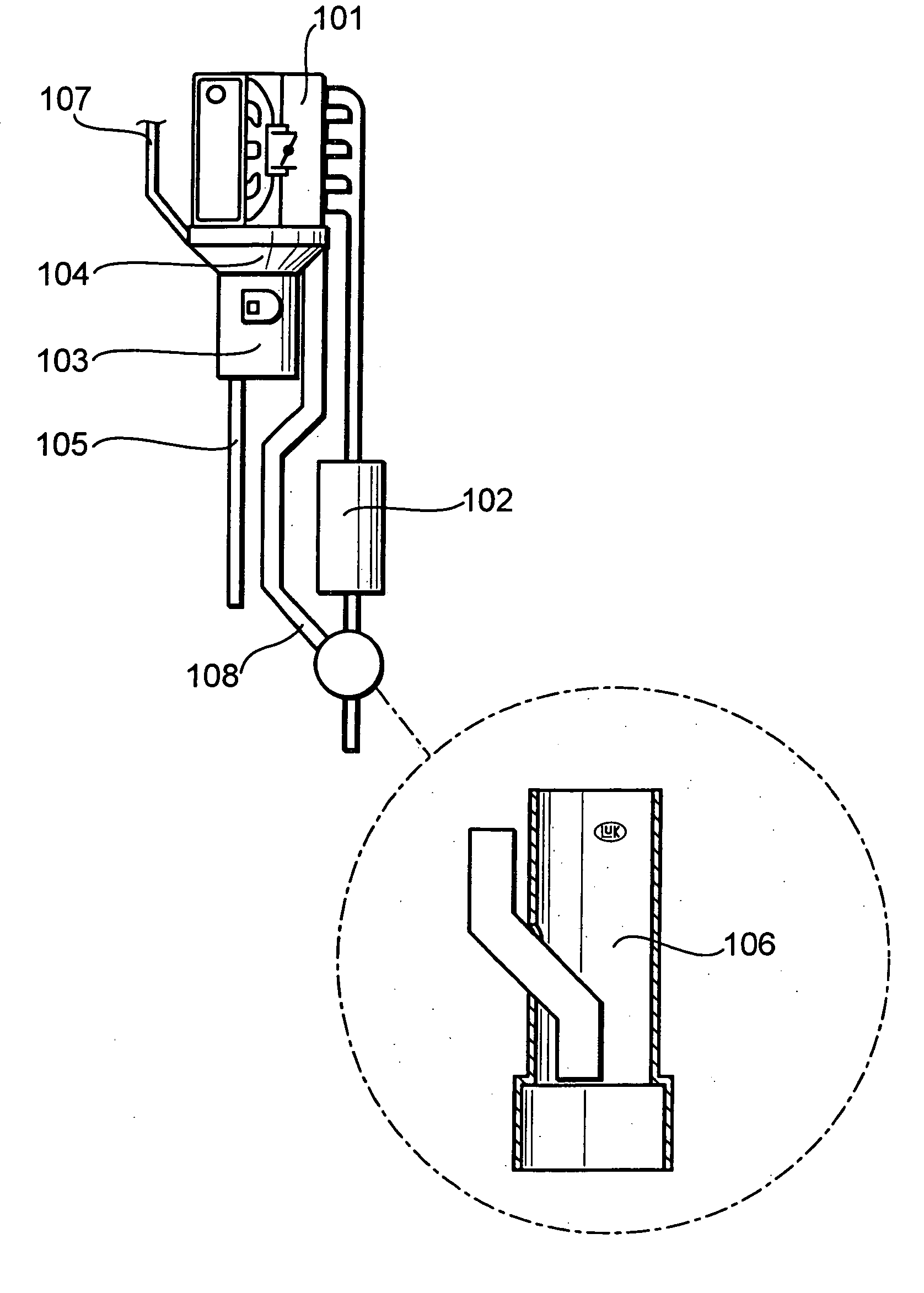
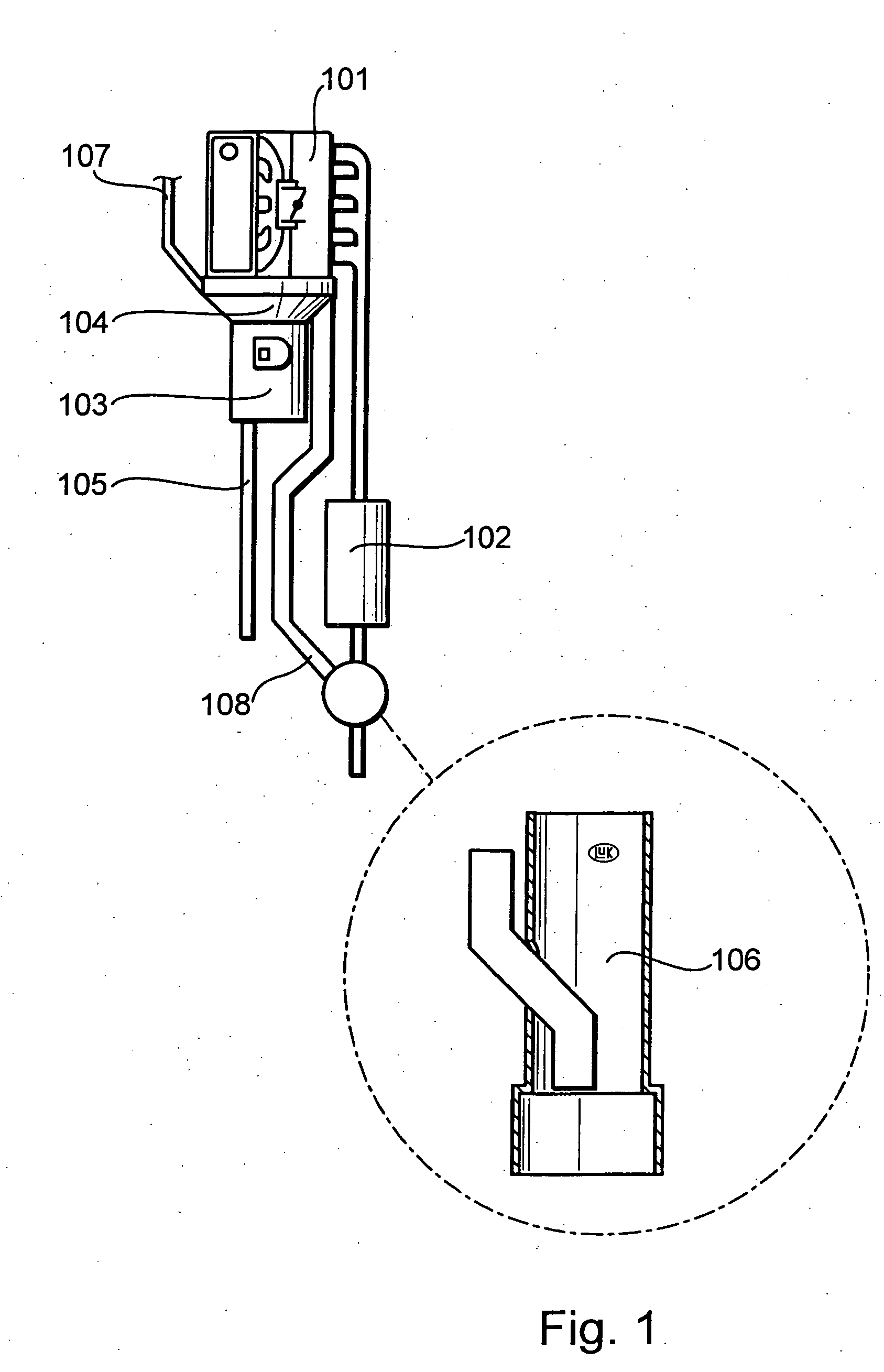
[0031] There is shown in FIG. 1 one possible embodiment of a system in accordance with the invention to cool a clutch, whereby an engine 101 with a connected exhaust gas system 102, and a transmission 103 with a clutch bell 104, as well as a drive shaft 105, are shown in schematically. In addition, there is shown in FIG. 1 an exemplary existing air inlet 107, for example for the windshield for ventilating the motor vehicle interior, which is utilized additionally for the cooling airflow in accordance with the invention. Other air inlets can also be provided for the cooling airflow.

[0032] The cooling airflow can be withdrawn from the clutch bell 104 by means of at least one air outlet 108 through a jet pump 106. The jet pump 106 is located in the exhaust system 102, and which is shown larger in the FIG. 1 enlargement portion.

[0033] The system in accordance with the invention, by interconnection with the existing air inlet system and exhaust gas system provided in the motor vehicle,...


PUM

PropertyMeasurementUnit
speedaaaaaaaaaa
frictionaaaaaaaaaa
frictional torqueaaaaaaaaaa

Abstract

A method and apparatus for reducing the thermal load on a motor vehicle clutch system. The clutch includes at least a pressure plate, a clutch disk, and a flywheel, by way of which a torque is transmitted. The friction forces that exist on the respective friction surfaces of the clutch disk are unevenly distributed. The clutch is cooled by a flow of cooling air that is led through the clutch bell that encloses the clutch and that defines a housing. The cooling air is conducted from the existing ventilation air inlets of the vehicle, and a jet pump arranged in the exhaust system is disclosed for withdrawing the cooling air from the clutch housing.

Description

BACKGROUND OF THE INVENTION [0001] 1. Field of the Invention [0002] The present invention relates to a method for the reduction of thermal loads and a method for cooling clutch systems, as well as a system therefor. [0003] 2. Description of the Related Art [0004] It has been shown that the thermal economy in clutch systems, such as, for example, a dry friction clutch, is problematic, especially at high power input. A thermal overload is especially to be suspected in a load-shift clutch of an uninterruptible transmission (USG). [0005] The components of the clutch, especially the friction lining, have a limited temperature resistance, and the energy input is very high in relation to the available space, whereby the heat transfer to the environment is too low. [0006] In addition, the pressure plate, for example, has a smaller heat capacity in contrast to the flywheel of the clutch. Furthermore, the heat flow to the surrounding parts is relatively low and the heat transfer to the surrou...

Claims


Application Information

Patent Timeline
Patent Type & Authority Applications(United States)
IPC IPC(8): B60K13/04B23P21/00B60K17/00B60K17/02B60K17/08B60W10/00B60W10/02B60W10/04B60W10/10B62D65/10F02D29/00F02D35/00F16D13/22F16D13/58F16D13/60F16D13/64F16D13/72F16D48/02F16D48/06F16H3/00F16H3/089F16H3/091F16H3/093F16H3/12F16H61/04F16H61/66F16H61/68F16H61/684F16H63/00F16H63/16F16H63/40
CPCB60K13/04B60K17/02F16D13/58F16D13/64F16D13/72F16D2300/12Y10T477/677Y10T29/49822Y10T29/49904Y10T29/4984Y10T477/688Y10T29/49815Y10T29/49826
Inventor SCHNEIDER, MATTHIASAHNERT, GERDLANG, DIETMARPOLLACK, BURKHARD
Owner LUK LAMELLEN & KUPPLUNGSBAU BETEILIGUNGS KG
Learn More