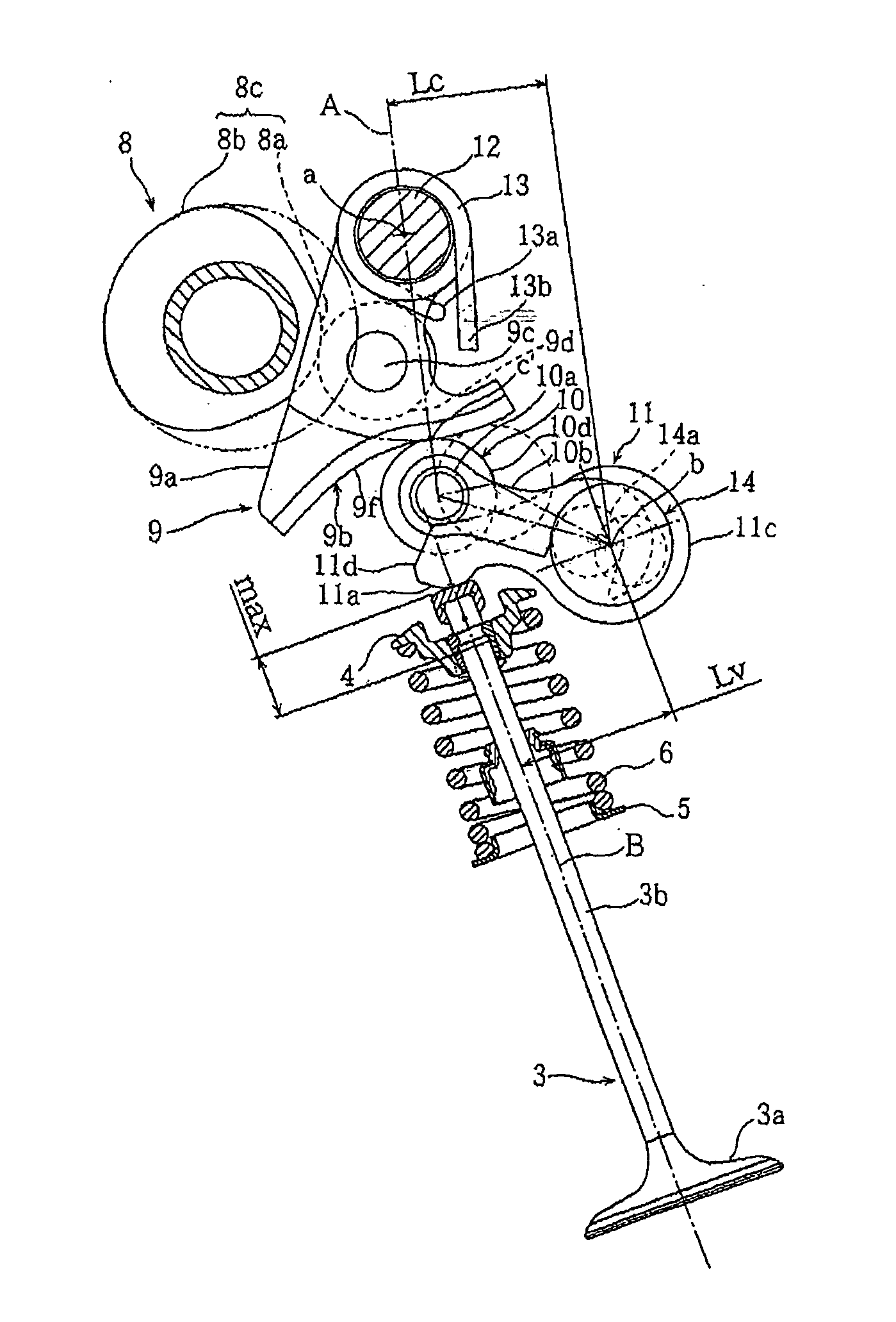
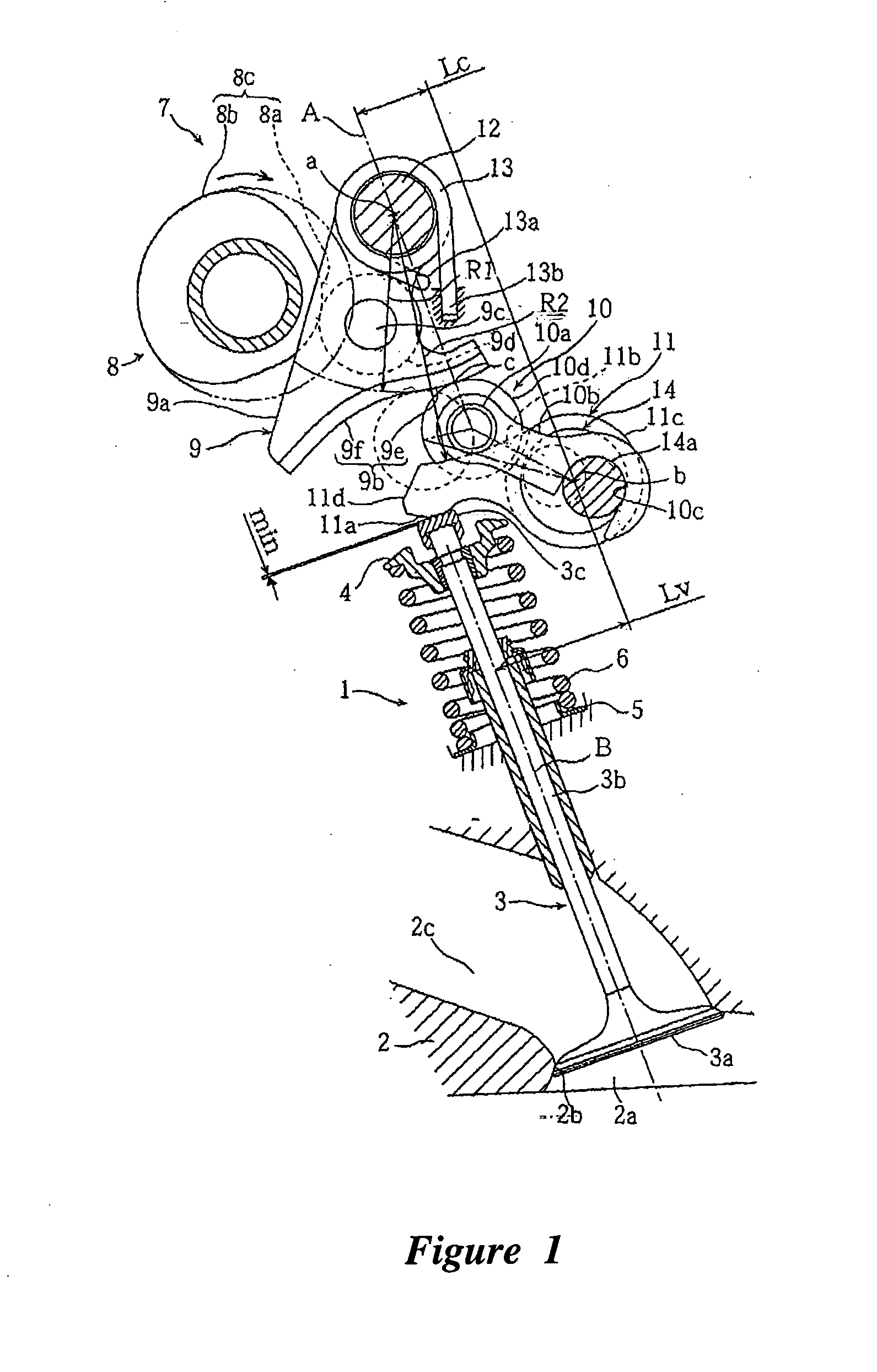
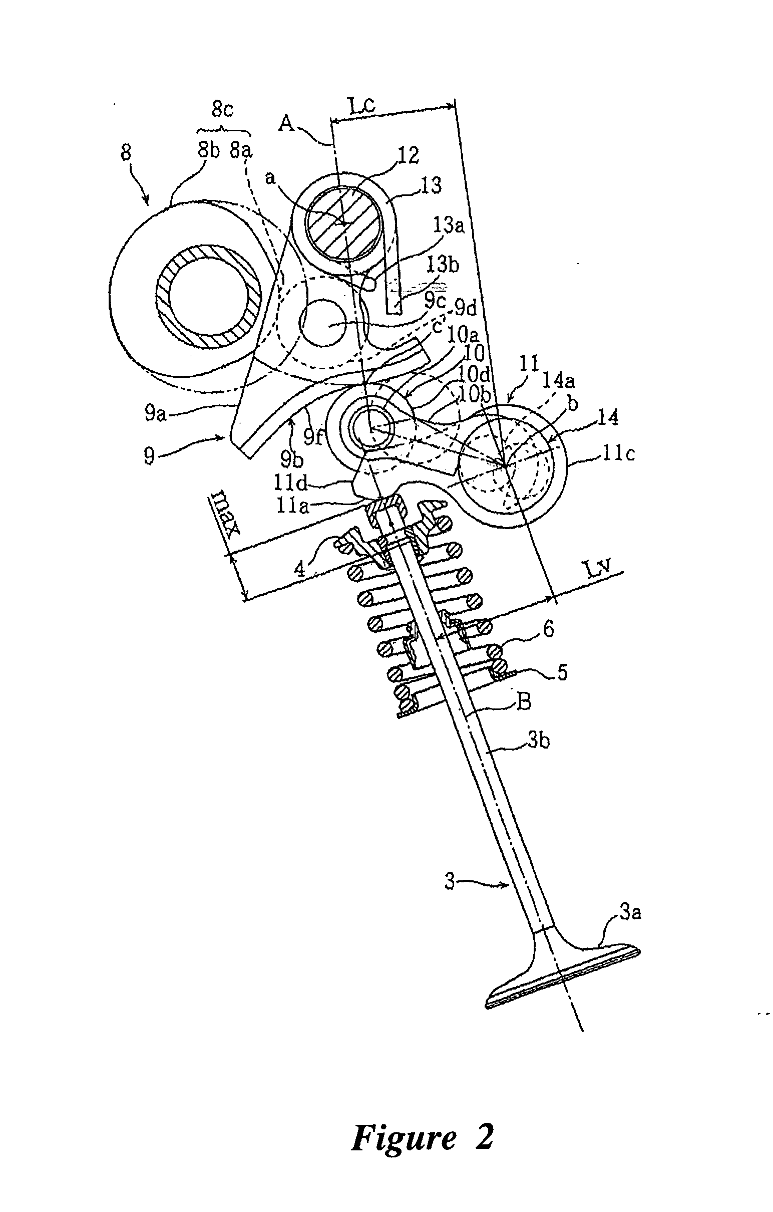
Valve train device for an engine
a technology for valve trains and engines, applied in the direction of valve details, valve arrangements, valve drives, etc., can solve the problems of reduced pumping loss, difficult to secure the rigidity of the entire valve opening/closing device, and difficult to secure the valve li
- Summary
- Abstract
- Description
- Claims
- Application Information
AI Technical Summary
Benefits of technology
Problems solved by technology
Method used
Image
Examples
second embodiment
[0056]FIGS. 6 and 7 are drawings for describing a second embodiment according to the invention, in which the same reference numerals and symbols as those in FIGS. 1 and 2 represent the same parts or the equivalents.
[0057] The second embodiment is an example in which the camshaft is of crankshaft type. That is, a crankshaft (camshaft) 18 includes a drive shaft 19a and a disk-like cam plate 19b, which is formed midway of the drive shaft 19a in one body and located eccentrically relative thereto. To the cam plate 19b is rotatably mounted a base 20a of a plate-like connecting rod 20, the distal end 20b of which is also rotatably coupled with a roller shaft 9c of the swinging member 9.
[0058] In the second embodiment, rotation of the drive shaft 19a eccentrically rotates the cam plate 19b about the axis (d). The connecting rod 20 oscillates the swinging member 9, and this swinging motion causes the rocker arm 11 to open and close the intake valve 3 through the intermediate rocker member ...
third embodiment
[0060]FIGS. 8 and 9 are drawings for description of a third embodiment according to the invention, in which the same reference numerals and symbols as those in FIGS. 1 and 2 represent the same parts or the equivalents.
[0061] The third embodiment is an example in which separate valve train devices 7, 7 are provided for the right and left intake valves 3, 3′, respectively. Specifically, it is constituted such that a left cam nose 8c and a right cam nose 8c′ oscillate a left swinging member 9 and a right swinging member 9′, respectively, which in turn oscillate a left rocker arm 11 and a right rocker arm 1′, respectively, which subsequently advance and retract the intake valves 3, 3′, respectively, to thereby open and close the intake valve openings 2b, 2b′.
[0062] In the third embodiment, since the left and right valve train devices 7, 7′ are separately disposed, an appropriate geometry of the left and right cam noses 8c, 8c′, left and right swing cam faces 9b, 9b′, and left and right...
fifth embodiment
[0069]FIGS. 11 and 12 are drawings that depict a fifth embodiment according to the invention, in which the same reference numerals and symbols as those in FIGS. 1 to 10 represent the same parts or the equivalents.
[0070] The fifth embodiment is an example in which a roller 9d is attached to the swinging member 9 and rotationally contacts a cam nose 8c of a camshaft 8. A relative length Lc′ between an axis (d) of a roller shaft 9c of a roller 9d and an axis (a) of a swing shaft 12 of the swinging member 9 is variable. The roller 9d is guided by changing the relative length in the direction D, which is inclined relative to a straight line (E) connecting the axis (a) with the axis (d).
[0071] Specifically, a lever ratio. Lv / Lc′ of the swinging member when the valve opening duration is short is determined to be larger than that when the valve opening duration is long, where Lc′ is defined as a relative distance between the axis (a) of the swing shaft 12 of the swinging member 9 and the a...
PUM
 Abstract
Description
Claims
Application Information
 - R&D
- Intellectual Property
- Life Sciences
- Materials
- Tech Scout
- Unparalleled Data Quality
- Higher Quality Content
- 60% Fewer Hallucinations
Browse by: Latest US Patents, China's latest patents, Technical Efficacy Thesaurus, Application Domain, Technology Topic, Popular Technical Reports.
© 2025 PatSnap. All rights reserved.Legal|Privacy policy|Modern Slavery Act Transparency Statement|Sitemap|About US| Contact US: help@patsnap.com


