
Image forming apparatus

Inactive Publication Date: 2005-06-09
CANON KK
View PDF3 Cites 9 Cited by
  • Summary
  • Abstract
  • Description
  • Claims
  • Application Information

AI Technical Summary

Benefits of technology

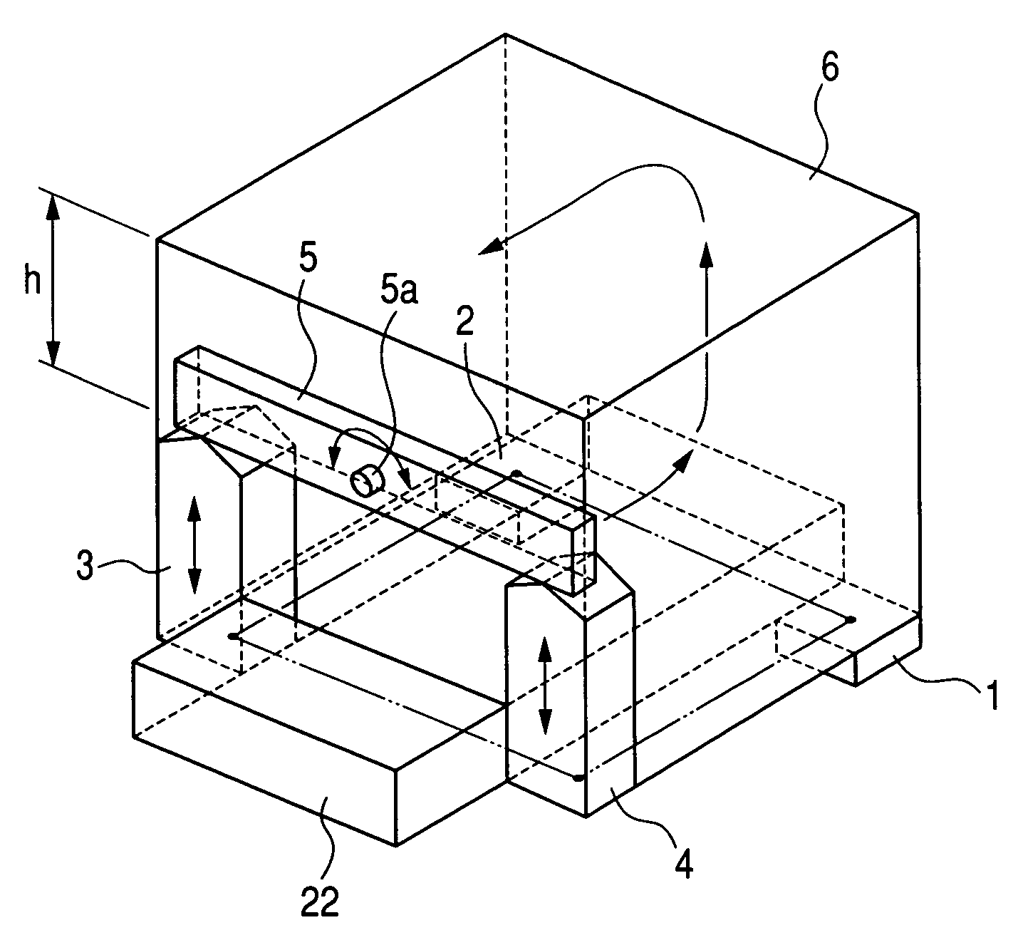
[0021] An object of the present invention is to prevent the deformation of an image forming apparatus when placed on an uneven surface, without increasing the load on its bottom plate.

Problems solved by technology

However, when the multicolor image forming apparatus is placed on an uneven surface, for example, on an area where it is placed with four placement points with only one point being different in a height level than the other points, the following problem arises.
Since the straight line connecting a point and another point of different height levels and the straight line connecting the two other points to be in parallel with each other become not parallel with each other, it results the occurrence of force that deforms the main body of the image forming apparatus.
The occurrence of deformation of the main body of the image forming apparatus change the positional relationship between the photosensitive drums and scanner as the exposure means for each color, depending on the strength of the bottom plate of the main body of the image forming apparatus, leading to misregistration in images.
As a result, the increase in the displacement force on the endless belt may cause the deterioration or breakage of end portion of the belt, affecting the life of the endless belt.
This results in the heavy weight of the main body and the increased cost for parts.
Further, the use of a drawing shape for improving the rigidity may badly affect the flatness and the dimension accuracy, resulting in the lowered accuracy in mounted position of the photosensitive drums or scanner.
Therefore, this presents a significant problem in developing a smaller-sized printer with a lower price and higher quality image, for which the market has a strong demand.
However, even if the placement point C is provided under the paper feeding cassette 22 as shown in FIG. 8A, using only the space under the paper feeding cassette 22 is not enough since substantial rigidity along edge line a is required for supporting the body.
Therefore, to secure the rigidity along edge line a, an expensive member having large section area must be applied to increase the rigidity of the bottom plate.
Moreover, expanding the space under the cassette 22 interferes with the object of using the arrangement with only three placement points to provide a smaller-sized, lower-price apparatus.
This causes the non-symmetrical deformation of the main frame, which directly leads to misregistration, the increase in displacement force on the endless belt, and inclined conveyance of recording paper.
Therefore, this arrangement is not feasible.

Method used


Image

  • Image forming apparatus
  • Image forming apparatus
  • Image forming apparatus

Examples


Embodiment Construction

[0032] Embodiments of the present invention will be described with reference to appended drawings.

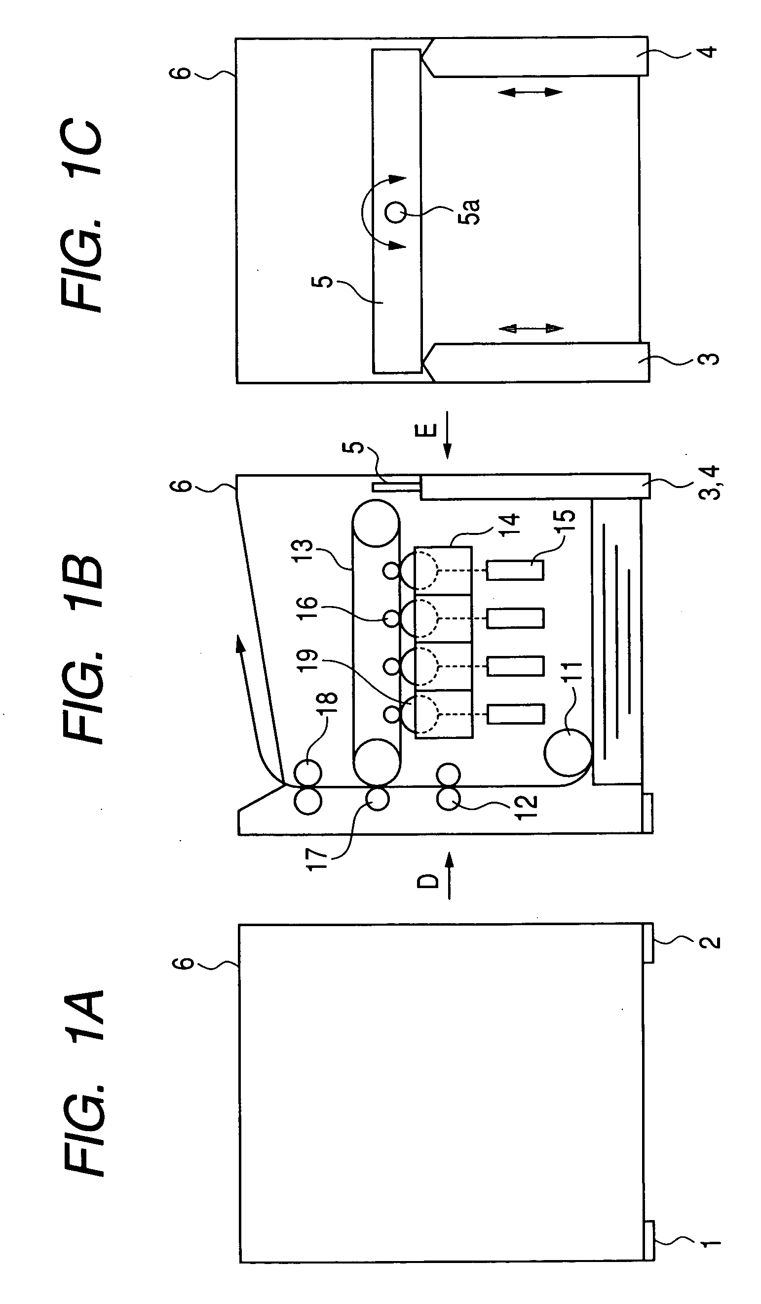
[0033]FIGS. 1A to 1C show an indirect-transfer-type, full-color image forming apparatus employing electrophotography: FIG. 1A is a diagram when viewing FIG. 1B in the direction of arrow D; FIG. 1B is a schematic section diagram; and FIG. 1C is a diagram when viewing FIG. 1B in the direction of arrow E.

[0034] In FIGS. 1A, 1B and 1C, reference numeral 11 denotes paper feeding means for separating stacked paper sheets and feeding them; reference numeral 12 denotes a registration roller for detecting the leading edge of a paper sheet and conveying the paper sheet in synchronization with an image signal; reference numeral 13 denotes a transfer belt for forming an intermediate image as an intermediate transfer member; reference numeral 14 denotes a developing device as developing means having four photosensitive drums 19 as image bearing members arranged substantially in horizontal directio...


PUM


Abstract

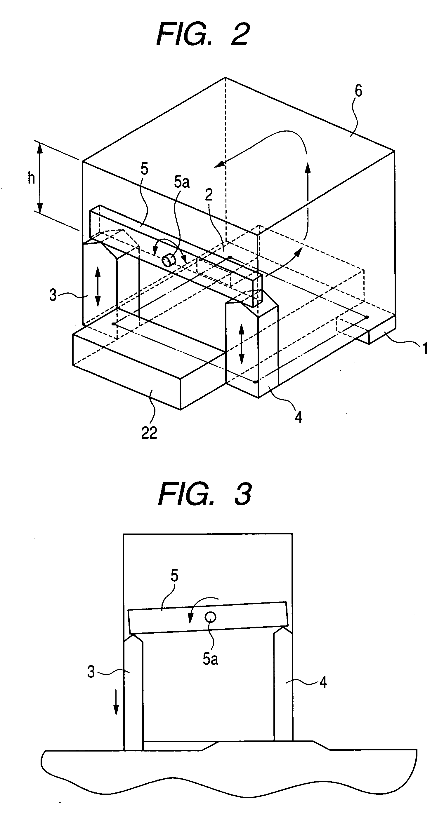
The image forming apparatus includes a first placement member, a second placement member, a third placement member and a fourth placement member which contact with a placement surface for placing the image forming apparatus thereon, and which support the image forming apparatus, a side plate of the image forming apparatus, and supporting means as the supporting member for supporting the third placement member and the fourth placement member movably in a vertical direction of the image forming apparatus. This can prevent the deformation of the image forming apparatus without increasing the load on a bottom plate.

Description

BACKGROUND OF THE INVENTION [0001] 1. Field of the invention [0002] The present invention relates to a placement structure for a monochromatic image forming apparatus or a full-color image forming apparatus employing electrophotography. [0003] 2. Related Background Art [0004] In the field of image forming apparatuses employing electrophotography such as full-color printers, a smaller-sized printer with a lower price and higher image quality is required by the market, in particular, as more and more personal computers are being generally used. [0005]FIGS. 5A and 5B are schematic section diagrams of an indirect-transfer-type, full color image forming apparatus that employs electrophotography. [0006] In FIGS. 5A and 5B, reference numeral 11 denotes paper feeding means for separating stacked paper sheets and feeding them; reference numeral 12 denotes a registration roller for detecting the leading edge of a paper sheet and conveying the paper sheet in synchronization with an image signa...

Claims


Application Information

Patent Timeline
IPC IPC(8): G03G15/00B41J29/06
CPCG03G15/00
Inventor NISHITANI, HITOSHIMUNAKATA, ATSUSHI
Owner CANON KK
Learn More