
Information transmission system, information sending device, information receiving device, information transmission method, information sending method, information receiving method and program product

Active Publication Date: 2012-12-27
CASIO COMPUTER CO LTD
View PDF8 Cites 129 Cited by
  • Summary
  • Abstract
  • Description
  • Claims
  • Application Information

AI Technical Summary

Benefits of technology

[0021]An object of the present invention is to enable the decoding of multivalued optical transmission information without increasing processing load.

Problems solved by technology

Therefore, there is a problem in that, when signals (binary modulation signals) generated by binary blinking of light are received by a popularized camera having a common frame rate (about 30 fps) and information is reproduced, a considerable amount of time is required (about two seconds, described in detail hereafter).
Although modulation of multivalued light using a combination of the colors red (R), green (G), and blue (B) as in the other known technologies can be performed to solve this problem, simply performing the value multiplexing increases processing load on the light receiving device.

Method used


Image

  • Information transmission system, information sending device, information receiving device, information transmission method, information sending method, information receiving method and program product
  • Information transmission system, information sending device, information receiving device, information transmission method, information sending method, information receiving method and program product
  • Information transmission system, information sending device, information receiving device, information transmission method, information sending method, information receiving method and program product

Examples


Embodiment Construction

[0055]An embodiment of the present invention will be described with reference to the drawings.

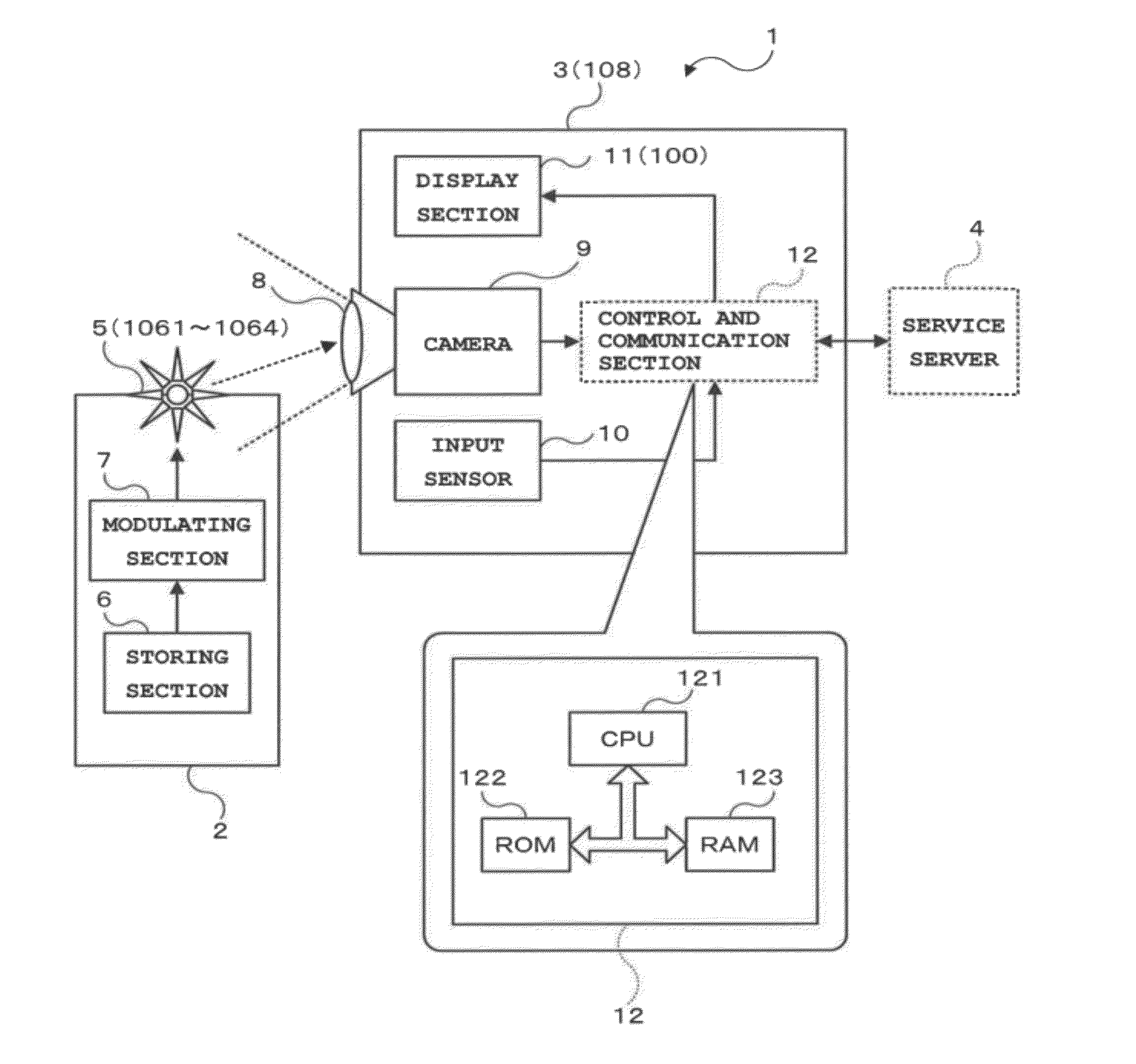
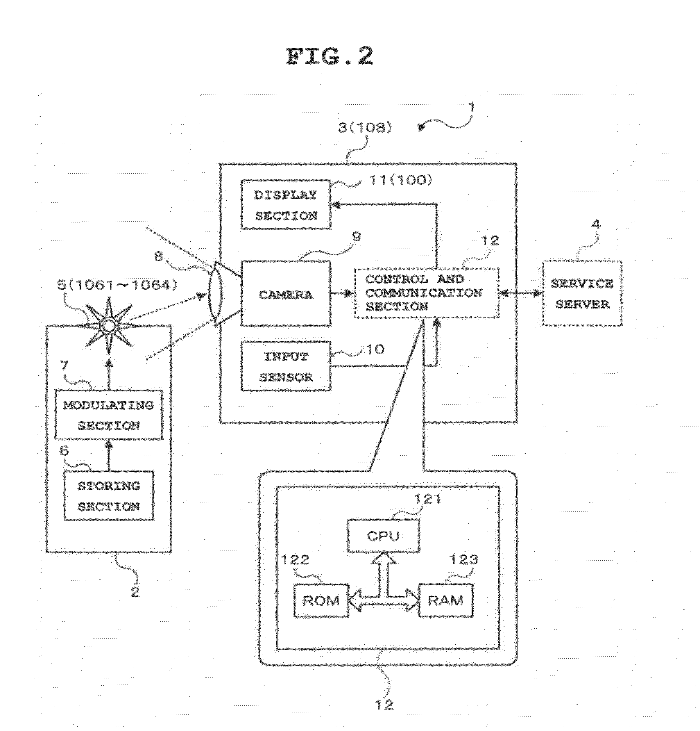
[0056]FIG. 2 is a block diagram of an information transmission system used in FIG. 1. In FIG. 2, the information transmission system 1 includes a light emitting device 2, a light receiving device 3 and a service server 4.

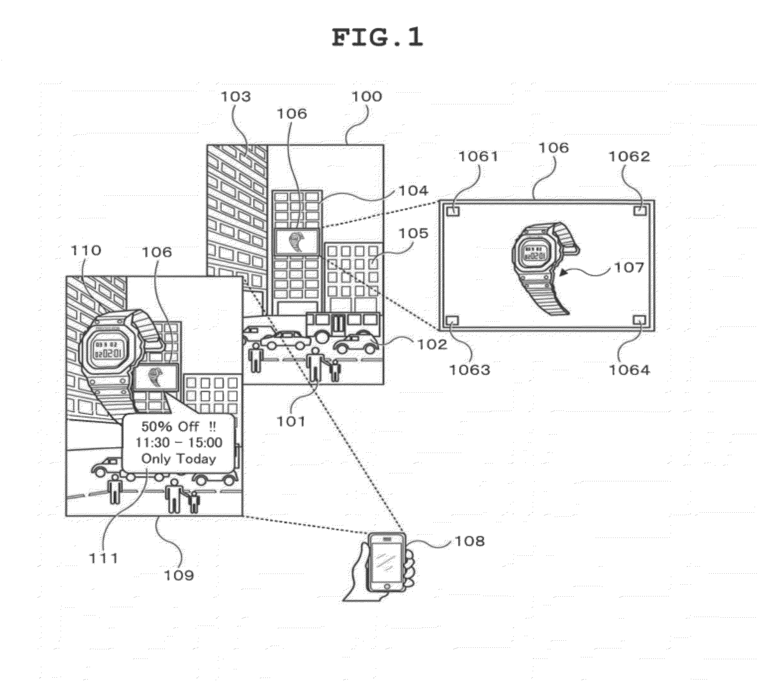
[0057]The light emitting device 2 includes a light emitting section 5, a storing section 6 that stores information such as tag identification (ID), and a modulating section 7 for modulation-driving the light emitting section 5 (equivalent to 1061 to 1064 in FIG. 1) using information stored in the storing section 6, and is provided in a system for transmitting information by a display terminal 106, in locations such as outdoors, transportation facilities, storefronts, and public facilities.

[0058]The light emitting section 5 transmits required information (such as tag ID) based on the manner of light emission by the light emitting section 5 (temporal color change of emitted l...


PUM


Abstract

An information transmission system is constituted by: an information sending device including a light emitting section that emits light in a plurality of colors, a modulating section that modulates information to be transmitted into signals composed of changes in color, and a light emission control section that controls the light emitting section to emit light while changing color temporally based on the signals generated by the modulating section; and a receiving device including a camera that captures an image having color, and a control and communication section that detects a temporal color change of the light emitting section emitting light by light emission control by the information transmitting device, from images consecutively captured by the camera, decodes the detected color change into information, and outputs the generated information to a display section.

Description

CROSS-REFERENCE TO RELATED APPLICATIONS[0001]This application is based upon and claims the benefit of priority from the prior Japanese Patent Applications No. 2011-139213 and No. 2011-139233, both filed Jun. 23, 2011, the entire contents of which are incorporated herein by reference.BACKGROUND OF THE INVENTION[0002]1. Field of the Invention[0003]The present invention relates to an information transmission system, an information sending device, information receiving device, an information transmission method, an information sending method, an information receiving method, and a program product using a spatial optical transmission technology.[0004]2. Description of the Related Art[0005]In recent years, so-called digital signage is gaining attention as an information transmission system using a spatial optical transmission technology. The digital signage refers to a system for transmitting information in a location other than home, such as outdoors, transportation facilities, storefron...

Claims


Application Information

Patent Timeline
IPC IPC(8): H04B10/10H04B10/04H04B10/06
CPCH04B10/1129H04B10/116H04B10/516H04B10/69H04B10/11H04B10/548H04N1/46
Inventor IIZUKA, NOBUOKANEKO, KEIICHIKIKUCHI, MASAAKI
Owner CASIO COMPUTER CO LTD
Learn More