Eureka AIR delivers breakthrough ideas for toughest innovation challenges, trusted by R&D personnel around the world.

Power supply device and electronic equipment comprising same

a technology of power supply device and electronic equipment, which is applied in the direction of electric variable regulation, process and machine control, instruments, etc., can solve the problem of large drop in the voltage of the input power supply (vtt_in), and achieve the effect of eliminating the possibility of malfunction and high-security operation

Active Publication Date: 2005-06-09
ROHM CO LTD
View PDF11 Cites 33 Cited by
  • Summary
  • Abstract
  • Description
  • Claims
  • Application Information

AI Technical Summary

Benefits of technology

[0016] With the foregoing in view, it is an object of the present invention to provide a power supply device for controlling the charging current that flows through the transistor for feeding immediately after recovery from the shutdown status, so as to suppress the voltage drop of the input power supply, and the electronic equipment using this power supply device.
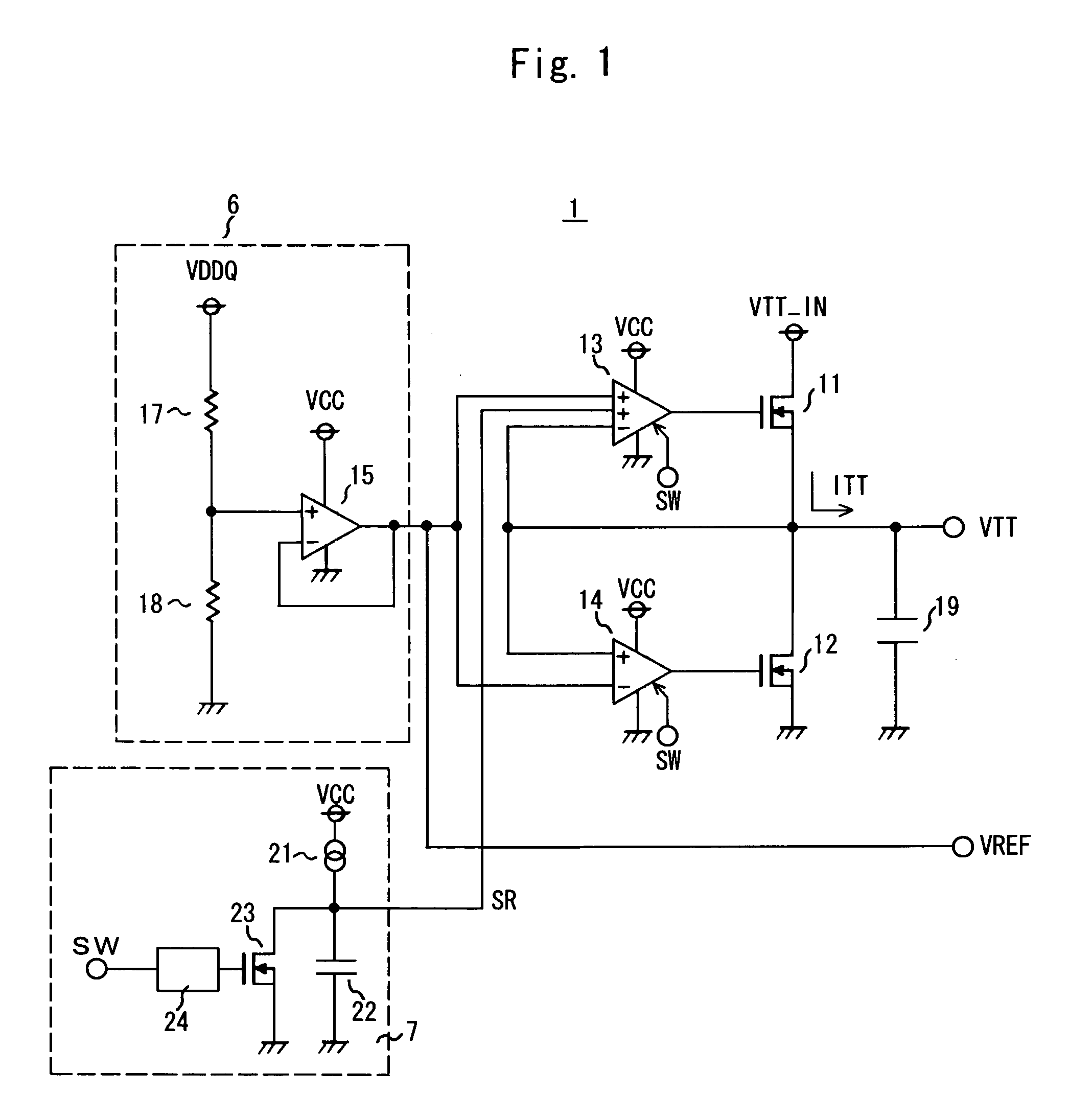
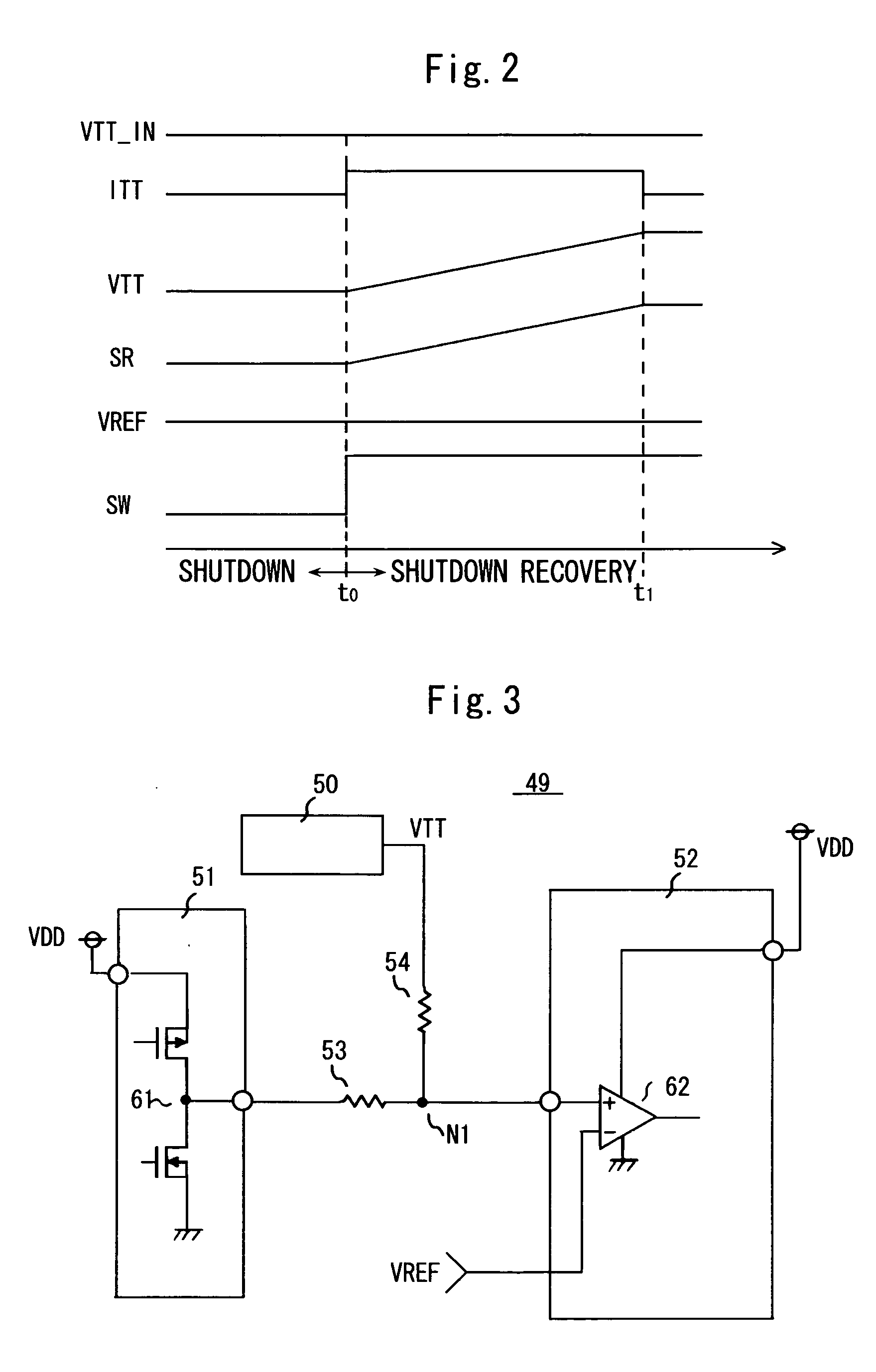
[0019] In the power supply device according to the present invention, the first differential amplification circuit controls the transistor for feeding (first transistor) by comparing the voltage, which gradually rises from the shutdown recovery circuit, and the output power supply voltage (power supply voltage for termination) immediately after recovery from shutdown, so the charging current that flows through the transistor for feeding becomes roughly constant, and the voltage drop of the input power supply is suppressed to almost zero. The electronic equipment according to the present invention enables a highly secure operation, eliminating the possibility of malfunction caused by a voltage drop of the input power supply immediately after recovery of shutdown by using this power supply device.

Problems solved by technology

As a result, the drop in the voltage of the input power supply (VTT_IN) becomes quite large.

Method used


Image

  • Power supply device and electronic equipment comprising same
  • Power supply device and electronic equipment comprising same
  • Power supply device and electronic equipment comprising same

Examples


Embodiment Construction

[0025] Embodiments of the present invention used for the above mentioned electronic equipment shown in FIG. 3 will now be described with reference to the drawings. FIG. 1 is a circuit diagram of the power supply device 1 which is an embodiment of the present invention.

[0026] The power supply device 1 which is a so called push-pull type, just like the power supply device 101 of the related art, outputs the output power supply voltage, that is the power supply voltage for termination (VTT) from the power supply voltage output terminal for termination (VTT output terminal) and the reference voltage (VREF) from the reference voltage output terminal (VREF output terminal), and comprises a reference voltage generation circuit 6 for generating reference voltage (VREF), an NMOS type transistor for feeding (first transistor) 11 disposed between the input power supply (VTT_IN) and the VTT output terminal, an NMOS type transistor for discharging (second transistor) 12 disposed between the gro...


PUM


Abstract

The present invention provides a power supply device which can suppress a voltage drop of the input power supply immediately after recovery from shutdown status. The power supply device comprises a reference voltage generation circuit for generating reference voltage (VREF), a transistor for feeding disposed between an input terminal (VTT_IN) and an output terminal (VTT output terminal), a transistor for discharging disposed between a ground potential and a VTT output terminal, a first and second differential amplification circuits for controlling the transistors for feeding and discharging respectively by inputting the output power supply voltage (VTT) as feedback and comparing it with VREF, and a shutdown recovery circuit for generating voltage that gradually starts up by a constant current source and a capacitor, wherein the first differential amplification circuit compares VTT with the voltage (SR) of the shutdown recovery circuit instead of VREF, for a certain period from the point of recovery from shutdown status.

Description

BACKGROUND OF THE INVENTION [0001] 1. Field of the Invention [0002] The present invention relates to a push-pull type power supply device suitable for a high-speed memory device and electronic equipment which comprises this power supply device and uses the output thereof for the power supply for termination. [0003] 2. Description of the Related Art [0004] Recently the development of memory devices in attempts to further increase data transfer speed is actively on-going as the performance of electronic equipment progresses. Of this equipment, a DDR (Double Data Rate) synchronous DRAM (DDR-SDRAM) has been commercialized, which synchronizes data transfer for both edges, rise and fall, of a clock signal, to increase the data transfer speed of a synchronous DRAM (SDRAM), which operates synchronizing clock signals. [0005] In a DDR-SDRAM, a high-speed interface with small amplitude signals using the power supply voltage for termination and reference voltage, is used for the high-speed data...

Claims


Application Information

Patent Timeline
Patent Type & Authority Applications(United States)
IPC IPC(8): G05F1/56G05F1/40G05F1/618G11C5/14H02M3/155H03F3/30
CPCY10S323/901G05F1/56G11C5/14
Inventor SAKAI, MASARUOKUBO, TAKUYA
Owner ROHM CO LTD
Why Eureka
Eureka Blog
Learn More