
Concrete anchor float

a technology of concrete anchors and floats, which is applied in the direction of girders, joists, trusses, etc., can solve the problems of affecting the integrity of the structure, affecting the ability of the anchor bolt to secure the sole plate to the foundation, and the anchor bolts have a tendency to sink or tilt away from vertical

Inactive Publication Date: 2005-06-09
BUILDING CONSTR SOLUTIONS
View PDF21 Cites 24 Cited by
  • Summary
  • Abstract
  • Description
  • Claims
  • Application Information

AI Technical Summary

Benefits of technology

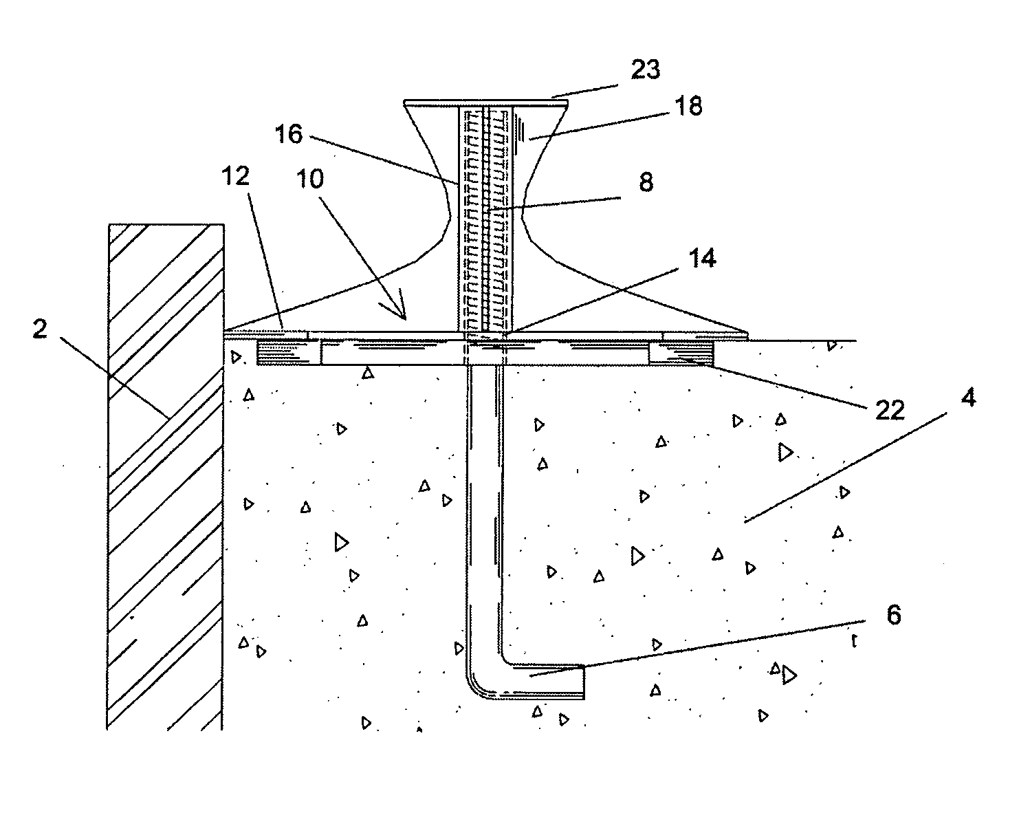
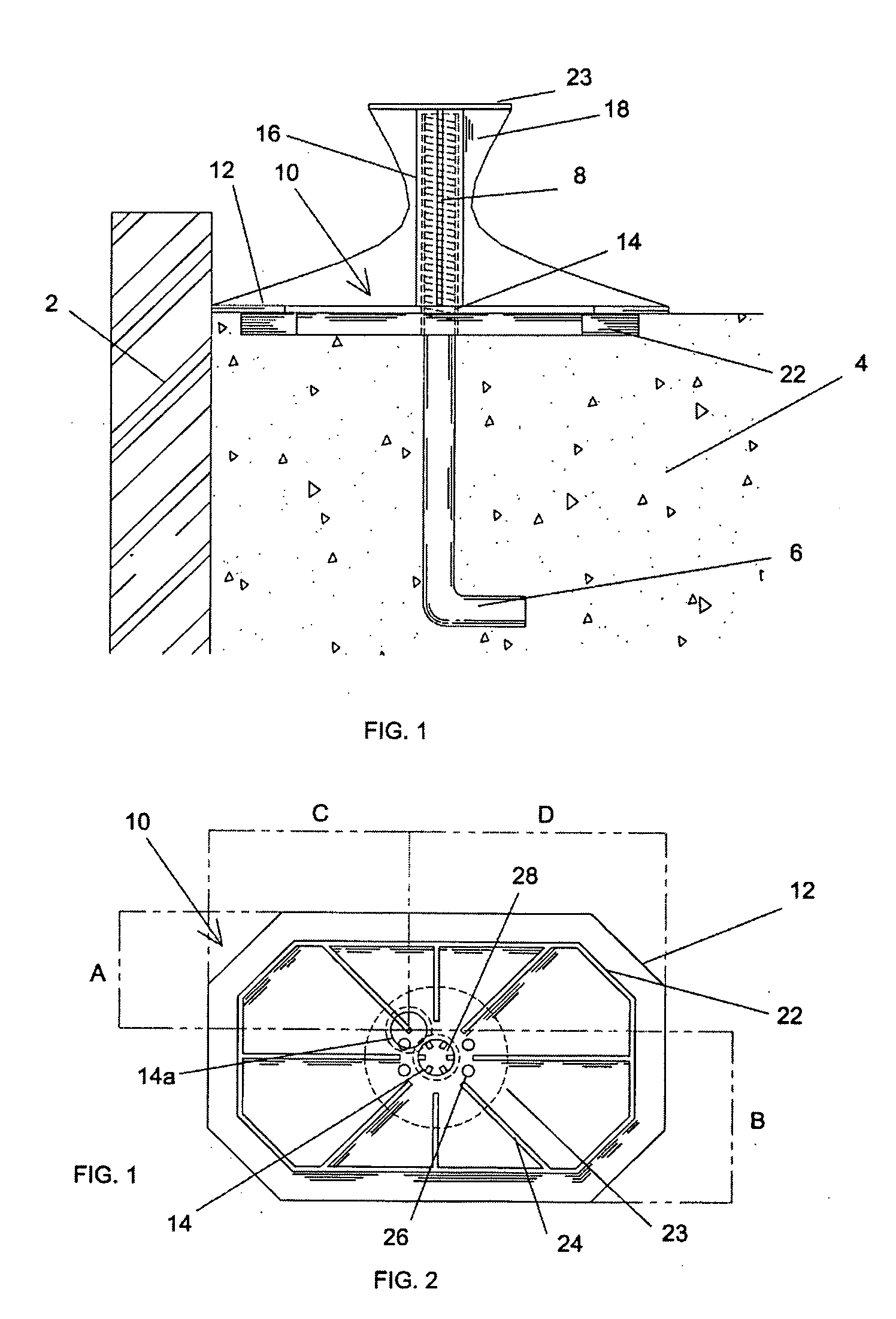
[0011] The present invention provides a concrete anchor float that, in one embodiment, facilitates the placement of anchor bolts that protrude from concrete constructions, such as foundations or footings for support posts. The concrete anchor float of the present invention can be used with nearly any conventional anchor bolt to insure the correct placement and alignment of the anchor bolt and to promote a strong bond between the anchor bolt and the concrete. According to an embodiment of the present invention, the concrete anchor float generally comprises a base plate with a hole, and a cap extending from the base plate over the hole. The cap includes a cavity configured to releasably secure the anchor bolt, and a top against which the anchor bolt rests upon insertion. According to an implementation of the present invention, the base plate includes features that minimize voids and air pockets between the anchor bolt and the concrete to promote a strong bond. In other implementations, the concrete anchor float includes an impalement protection surface that prevents serious injury that may otherwise result from falling on the anchor float.

Problems solved by technology

If the anchor bolts are not vertical or are not aligned properly, they create alignment problems, forcing the holes in the sole plate to be off of the center line.
This circumstance may cause the sole plate and the connection to the foundation to be weakened, detrimentally affecting the integrity of the structure.
In addition, if an anchor bolt protrudes too far above the sole plate, the anchor bolt is probably not embedded deeply enough in the concrete, which may also compromise the ability of nut to secure the sole plate to the foundation due to thread run out on the bolt shaft.
Furthermore, if the anchor bolt does not protrude far enough, the builder will have to chisel or auger a large portion of the sole plate out to create a large cupped-out area with potentially multiple drill holes to correctly locate the low bolt to attach the washer and nut.
If the concrete is too wet, the anchor bolts have a tendency to sink or to tilt away from vertical.
If the concrete is too hard, placing the anchor bolts tends to create dimples or funnel-shaped depressions (or air pockets) around the anchor bolts.
These depressions and resultant stress frequently result in cracks, and a poor bond between the concrete and anchor bold.
In addition, placement of anchor bolts in this manner often results in the anchor bolts being either too close or too far from the edge of the foundation, creating alignment problems for attachment of the sole plate.
Another problem relating to placement of anchor bolts in this manner is possible damage to the threads of the anchor bolt after placement in the concrete, or the possibility of concrete becoming embedded in the threads.
Even if an anchor bolt is correctly placed in the concrete, the very act of placement may cause air pockets or dimples around the anchor bolt.
Anchor bolts, after placement in a concrete foundation, also raise safety issues.
Although OSHA regulations do not specifically identify anchor bolts as a potential hazard, there is obviously a possibility that workers, or even trespassers, on the building site could be injured by falling on an anchor bolt which may protrude 2″ to 4″ from the foundation.

Method used


Image

  • Concrete anchor float
  • Concrete anchor float
  • Concrete anchor float

Examples


Embodiment Construction

)

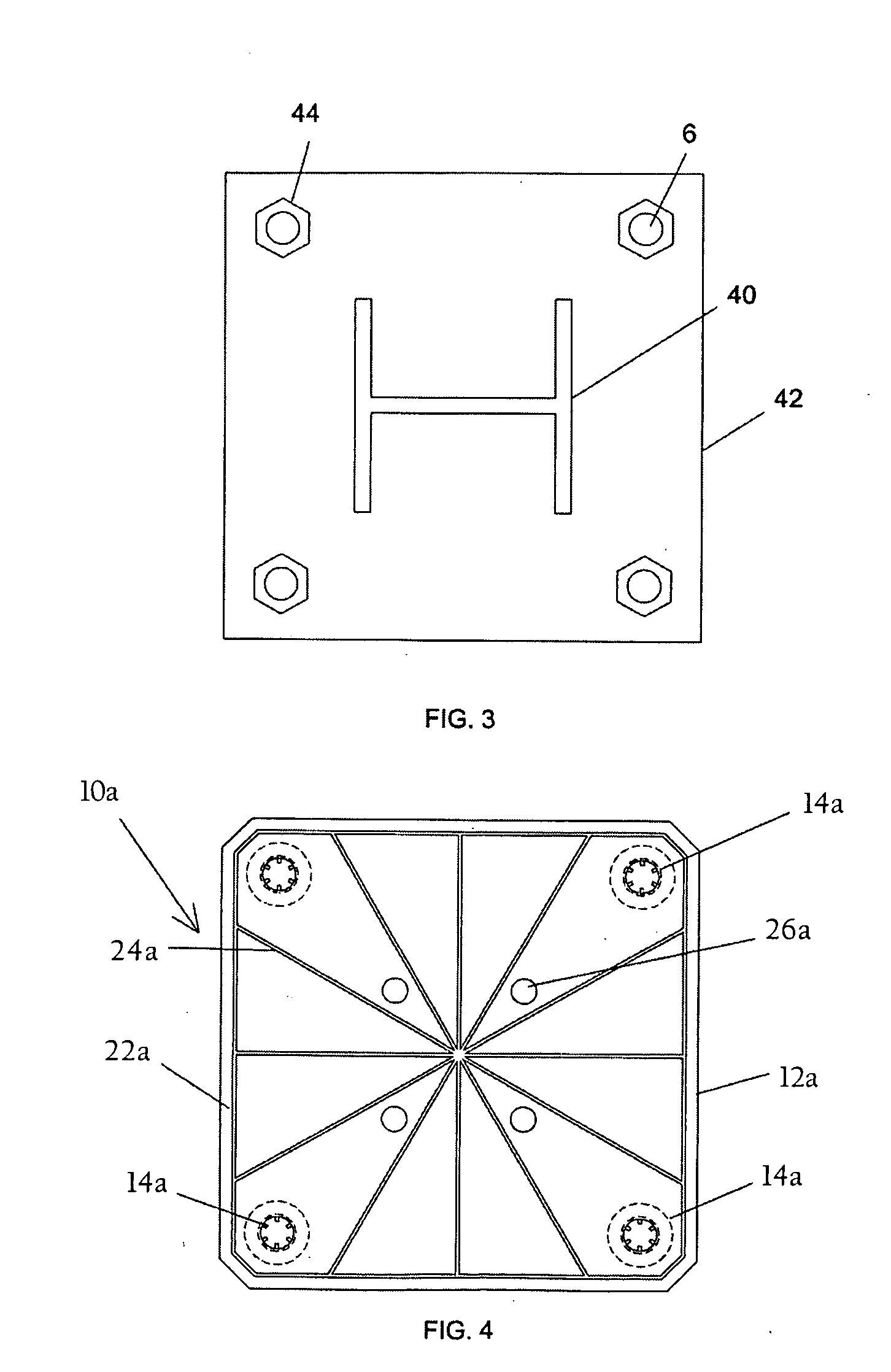
[0022] Referring to the drawings, FIGS. 1 and 2 illustrate the concrete anchor float according to an embodiment of the present invention. The concrete anchor float can be configured to be used with any number of conventional anchor bolts, and can be implemented in a variety of size configurations. In one embodiment described below, the concrete anchor float is configured to operate in connection with a single anchor bolt that is 1 / ″ in diameter. In other implementations, the present invention can be configured to operate in connection with rebar, or any other rod-shaped member. FIGS. 3 and 4 disclose a second embodiment of the concrete anchor float adapted for the placement of multiple anchor bolts in a pattern for installation of a column or post.

[0023] Now referring to FIGS. 1 and 5, a side and perspective view, respectively, of the concrete anchor float 10 is shown as it might be used in the construction of a typical concrete foundation. As FIGS. 1 and 6 illustrate, in most cas...


PUM


Abstract

A concrete anchor float that, in one embodiment, facilitates the placement of anchor bolts that protrude from concrete constructions, such as foundations. The concrete anchor float of the present invention can be used with nearly any conventional anchor bolt to insure the correct placement and alignment of the anchor bolt and to promote a strong bond between the anchor bolt and the concrete. According to an embodiment of the present invention, the concrete anchor float generally comprises a base plate with a hole, and a cap extending from the base plate over the hole. The cap includes a cavity configured to releasably secure the anchor bolt, and a top against which the anchor bolt rests upon insertion. According to an implementation of the present invention, the base plate includes features that minimize voids and air pockets between the anchor bolt and the concrete to promote a strong bond. In other implementations, the concrete anchor float includes an impalement protection surface that prevents serious injury that may otherwise result from falling on the anchor float.

Description

CROSS-REFERENCE TO RELATED APPLICATIONS [0001] The present application claims priority from U.S. provisional patent application Ser. No. 60 / 527,671 filed Dec. 5, 2003, and entitled “Concrete Anchor Float.”FIELD OF THE INVENTION [0002] The present invention relates to concrete construction and, more particularly, to a concrete anchor float facilitating placement and alignment of anchor bolts in concrete foundations and other constructions. BACKGROUND OF THE INVENTION [0003] In the United States and throughout the world, anchor bolts are the primary means of securing building structures to concrete foundations. Indeed, most building codes have detailed requirements for such anchor bolts and their placement in concrete constructions. For example, according to some building codes, these anchor bolts must be made of half-inch, L- or J-shaped steel rods, and embedded into the concrete at least six inches deep. In many cases, the structure placed atop the concrete foundation is anchored by...

Claims


Application Information

Patent Timeline
Patent Type & Authority Applications(United States)
IPC IPC(8): E04B1/41E04G21/18
CPCE04B1/4157E04G21/32E04G21/185E04C5/161E04G21/3252
Inventor ALYEA, MARK DUANETORPEY, BETH MARIEFISHER, ANDREW JOSEPHSLETTEN, MATTHEW AARONPINON, STEPHANIE NICOLE
Owner BUILDING CONSTR SOLUTIONS
Learn More