Organic light emitting display
a technology of organic light and display, applied in the direction of luminescnet screens, discharge tubes, identification means, etc., can solve the problems of deterioration of reducing the emission region, and reducing so as to improve the efficiency of organic light emitting display
- Summary
- Abstract
- Description
- Claims
- Application Information
AI Technical Summary
Benefits of technology
Problems solved by technology
Method used
Image
Examples
first embodiment
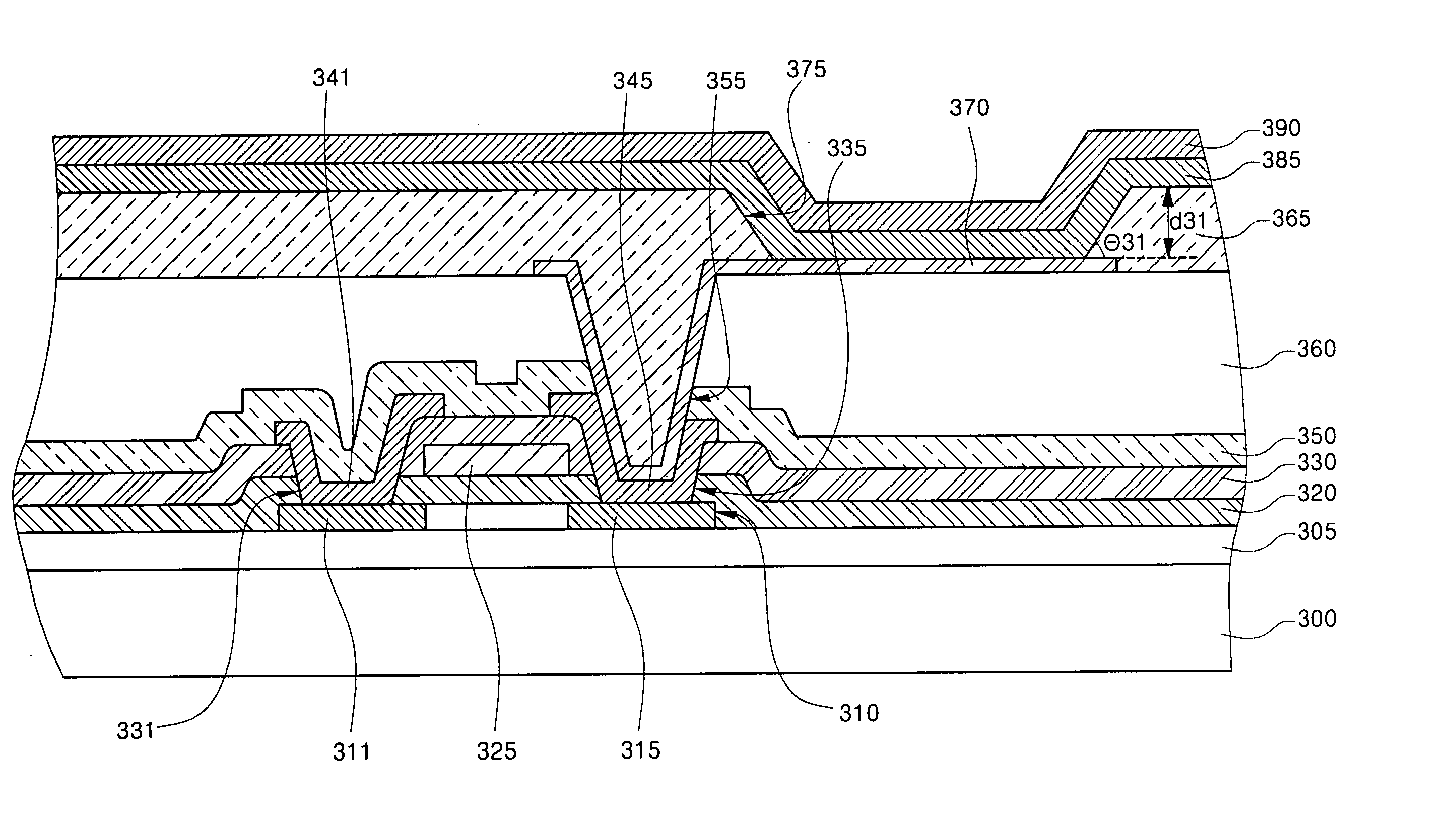
[0043]FIG. 7 is a cross-sectional view of a top-emission organic light emitting display according to the present invention. Referring to FIG. 7, a buffer layer 305 is formed on an insulating substrate 300, and a semiconductor layer 310 having source / drain regions 311, 315 is formed on the buffer layer 305. A gate electrode 325 is formed on a gate insulating layer 320, and source / drain electrodes 341, 345 connected to the source / drain regions 311, 315 through first holes 331, 335 are formed in an interlayer insulating layer 330.
[0044] A planarization layer 360 is formed on a passivation layer 350, and an anode 370, which is a lower electrode connected to one of the source / drain electrodes341, 345, for example, the drain electrode 345, through a second hole 355, is formed in the planarization layer 360. A pixel defining layer 365 including an opening 375 that exposes a portion of the anode 370 is formed on the planarization layer, and an organic thin film layer 385 and a cathode 390 a...
second embodiment
[0057]FIG. 8 is a cross-sectional view illustrating a top-emission organic light emitting display according to the present invention. Referring to FIG. 8, a buffer layer 405 is formed on an insulating substrate 400, and a semiconductor layer 410 including source / drain regions 411, 415 are formed on the buffer layer 405. A gate electrode 425 is formed on a gate insulating layer 420, and source / drain electrodes connected to the source / drain regions 411, 415 are formed in an interlayer insulating layer 430 through first holes 431, 435.
[0058] A planarization layer 460 is formed on a passivation layer 450, and an anode 470, which is a lower electrode connected to one of the source / drain electrodes 441, 445, for example, the drain electrode 445 through a second hole 455, is formed in the planarization layer 460. An organic thin film layer 485 and a cathode 490 are formed on the TFT substrate. The organic thin film layer 485 includes at least an emission layer selected from a hole injectio...
third embodiment
[0060]FIG. 9 is a cross-sectional view illustrating a bottom-emission organic light emitting display according to the present invention. Referring to FIG. 9, a buffer layer 505 is formed on an insulating substrate 500, and a semiconductor layer 510 including source / drain regions 511, 515 are formed on the buffer layer 505. A gate electrode 525 is formed on a gate insulating layer 520, and source / drain electrodes 541, 545 is formed in an interlayer insulating layer 530 through first holes 531, 535.
[0061] An anode 570, which is a lower electrode connected to one of the source / drain electrodes 541, 545, for example, the drain electrode 545, through a second hole 555, is formed in a passivation layer 550. A pixel defining layer 565 including an opening 575 that exposes a portion of the anode 570 is formed, and an organic thin film layer and a cathode 590, an upper electrode, are formed on the pixel defining layer 565 and the anode 570 of the opening 575. The organic thin film layer 585 ...
PUM
 Abstract
Description
Claims
Application Information
 - R&D
- Intellectual Property
- Life Sciences
- Materials
- Tech Scout
- Unparalleled Data Quality
- Higher Quality Content
- 60% Fewer Hallucinations
Browse by: Latest US Patents, China's latest patents, Technical Efficacy Thesaurus, Application Domain, Technology Topic, Popular Technical Reports.
© 2025 PatSnap. All rights reserved.Legal|Privacy policy|Modern Slavery Act Transparency Statement|Sitemap|About US| Contact US: help@patsnap.com


