
Gear unit of small motor

a gear unit and small motor technology, applied in the direction of gearing details, gearing, mechanical equipment, etc., can solve the problems of increasing the number of parts, high machining cost, heavy weight, etc., and achieve the effect of the cost, reducing the weight of the gear unit, and increasing production efficiency

Active Publication Date: 2005-06-02
MABUCHI MOTOR
View PDF13 Cites 3 Cited by
  • Summary
  • Abstract
  • Description
  • Claims
  • Application Information

AI Technical Summary

Benefits of technology

[0011] It is an object of the present invention to solve such problems, and to make it possible to construct the fixed shaft by deep drawing a plate-shaped member, to eliminate the need for corrosion prevention processing after machining, and not only to reduce the machining cost and material cost, but also to reduce the weight.
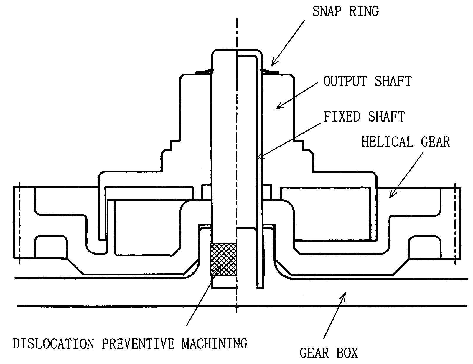
[0012] Also, it is an object of the present invention to eliminate the need for a special part or machining for preventing the helical gear, the output shaft and the like from coming off in the thrust direction, or preventing the fixed shaft from coming off from the gear box to thereby reduce the number of parts and facilitate assembly for reducing the cost.
[0015] Also, the fixed shaft can be constructed in a hollow and cylindrical shape by deep drawing a plate-shaped member, and at the time of the deep drawing, the structure can be arranged such that the fixed shaft is prevented from coming off from the gear box made of resin to be insert-molded through the use of a collar-shaped skirtlike portion to be formed on the outer periphery on the side of the opening of the fixed shaft. By boring a small hole in the ceiling surface of the fixed shaft, the structure can be arranged so as to breathe on insert molding.
[0017] According to the present invention, by making the fixed shaft into a hollow shaft, its weight could be reduced by about 60%. Also, through the use of a galvanized sheet, since the corrosion prevention effect can be expected, surface treatment after the machining becomes unnecessary, and it becomes possible to reduce the weight of the gear unit and the cost. By changing from the machining by a machine to deep drawing by a press, the production efficiency can be raised.
[0018] As regards fixing of the helical gear and the output shaft in the thrust direction, by changing into the hollow shaft, it becomes possible to use the snap ring, whereby there is no need for grooving, but the assembly man-hour can be reduced. Further, by changing into the hollow shaft, it becomes possible to subject the end of the fixed shaft to working such as cutting-staking and curling, whereby there is no need for a part such as the C-type snap ring which has been conventionally required, but it becomes possible to reduce the number of parts, and to further reduce the weight and the cost.

Problems solved by technology

Since it has been obtained by cutting steel material or the like as described above, the conventional fixed shaft has had drawbacks that it is high in machining cost, heavy in weight because of a solid shaft, and the material cost is also expensive.
Further, in order to prevent the helical gear, the output shaft and the like from coming off in the thrust direction, it is necessary to groove the fixed shaft and fix through the use of a C-type snap ring or the like, and therefore, the number of parts is increased, it takes time to assemble, and the cost is increased.

Method used


Image

  • Gear unit of small motor
  • Gear unit of small motor
  • Gear unit of small motor

Examples


Embodiment Construction

[0026] Hereinafter, on the basis of the exemplifications, the description will be made of the present invention. FIG. 1 is a view showing a first example of a gear unit portion embodying the present invention. FIGS. 1A and 1B exemplify the snap ring as seen from directions different from each other, and FIG. 1C exemplifies an essential portion of the gear unit in sectional view. The present invention is characterized by structure of the fixed shaft, the fixing structure of the fixed shaft to the gear box and the dislocation preventive structure of the output shaft from the fixed shaft, and as regards any structure other than these, the structure similar to such conventional structure as exemplified in FIG. 6 can be adopted.

[0027] Therefore, the helical gear exemplified in FIG. 1 is also, within the gear box made of resin as in the structure shown in FIG. 6, constructed so as to engage with a worm fixed near the tip portion of a motor shaft extended from the motor portion. Also, the...


PUM

PropertyMeasurementUnit
cylindrical shapeaaaaaaaaaa
weightaaaaaaaaaa
corrosionaaaaaaaaaa

Abstract

In the present invention, driving torque outputted from a motor portion is transmitted to a worm from a motor shaft, further to a helical gear from the worm, and is taken out to the outside from an output shaft which rotates together with the helical gear with a fixed shaft fixed to a gear box as a center. This fixed shaft is constructed in a hollow and cylindrical shape having an opening in which one end portion thereof has been opened, and a ceiling surface in which the other end portion thereof has been closed, and one end portion of this fixed shaft is subjected to dislocation preventive work, and is fixed to a gear box made of resin by pressing-in or insert molding. The other end portion of the fixed shaft is formed with the dislocation preventive structure of the output shaft and the helical gear installed to the fixed shaft.

Description

BACKGROUND OF THE INVENTION [0001] 1. Field of the Invention [0002] The present invention relates to a gear unit of a small motor in which driving torque outputted from a motor portion is taken out to the outside from an output shaft which rotates together with a helical gear, via a worm and the helical gear from a motor shaft further with a fixed shaft fixed to a gear box as a center. [0003] 2. Description of the Related Art [0004]FIG. 6 is a view exemplifying a small motor with a gear unit which has been generally used conventionally, FIG. 6A is a general view for the small motor with a gear unit, showing the gear unit portion in a partial sectional view, and FIG. 6B is a view exemplifying the gear unit portion shown in a partial sectional view as seen from a direction different from FIG. 6A. Also, FIGS. 7A and 7B are views exemplifying a C-type snap ring as seen from directions different respectively, and FIG. 7C is an enlarged view showing an essential part of FIG. 6B. [0005] As...

Claims


Application Information

Patent Timeline
Patent Type & Authority Applications(United States)
IPC IPC(8): F16H1/16F16H57/021F16H57/023H02K7/08H02K7/116
CPCF16H1/16F16H57/021H02K7/081Y10T74/19828Y10T74/2186Y10T29/4984Y10T29/49982Y10T409/10Y10T74/18792Y10T29/49885Y10T29/4998
Inventor OKUMURA, TAKESHIYAMAMOTO, KAZUYUKITANIGUCHI, SHINICHI
Owner MABUCHI MOTOR
Learn More