
Device for collecting statistical data for maintenance of small-arms

a technology for collecting statistical data and small arms, which is applied in the direction of measuring explosion force, force/torque/work measurement, instruments, etc., and can solve the problems of bursting of the barrel, no information can be provided that can be related to the and gradual wear of the barrel or the internal

Inactive Publication Date: 2005-05-26
ADVANCED DESIGN CONSULTING USA
View PDF29 Cites 51 Cited by
  • Summary
  • Abstract
  • Description
  • Claims
  • Application Information

AI Technical Summary

Benefits of technology

"The invention is a device that can be attached to a gun to collect data on its usage. The device is designed to be protected from the heat of the gun's barrel and has a sensor to detect impulses caused by firing. The device can store information about the gun's firing, including temperature, firing rate, and time data. It can also identify the weapon to which it is attached. The device has an interface to transfer data to a computer or other device for analysis. The technical effect of this invention is to provide a way to collect valuable information about small-arms usage and to improve the accuracy of gun safety and training."

Problems solved by technology

Although all of these devices are able to impart useful information about small-arms use over short periods none can provide information that can be related to wear of the barrel or internal mechanisms that are an essential part of any maintenance program.
Wear gradually degrades the accuracy of a firearm and in extreme cases can lead to the bursting of a barrel and injury to the shooter.
Wear can also lead to jamming, particularly in automatic and semi-automatic firearms.
The approach of Davis et al fails to take into account the effects of temperature on barrel wear.
If a series of rounds are fired the gun tube is heated and wear, which results from the abrasive properties of the propellant, corrosion by the expanding gases and thermal gradients through the tube wall, is greatly accelerated.
It is also of limited applicability to small-arms where the shock and vibration of ordinary handling could produce many false counts.
This purely mechanical system is relatively large and difficult to implement on small-arms.
It is also likely to undergo a change in threshold as the contact surface between the spring and the shaft wear during use.
Doubtless this device could be modified to count the cumulative number of shots fired, however, slide movement while unloaded or when chambering the first round from a new magazine will result in false counts.
In common with many of the previously described devices this counter cannot distinguish between the firing of a round, the chambering of the first round after the last shot in a magazine has been fired or the ejection of an unfired round.
None of the patents cited have means to measure this temperature nor do they have a way to determine the number of rounds fired at a particular temperature.
Further shortcomings of the aforementioned devices is their inability to be easily adapted for use on different weapons.
With the exception of Williams's device all are difficult to retrofit to a variety of small-arms.
Furthermore, those devices that utilize inertial switches, thereby avoiding the miscounts that are inherent in other sensing systems, cannot easily be altered to accommodate accessories such as night-vision scopes or noise suppressors that substantially change the mass of a weapon.

Method used


Image

  • Device for collecting statistical data for maintenance of small-arms
  • Device for collecting statistical data for maintenance of small-arms
  • Device for collecting statistical data for maintenance of small-arms

Examples


first embodiment

[0037] the invention utilizes a “hold-off delay” technique to sense shots fired by the firearm, and avoid miscounts due to extra impulses generated by the firearm during firing. A signal threshold is used to distinguish between signals which represent shots and extraneous impulses due to knocking the weapon against other objects or the like.

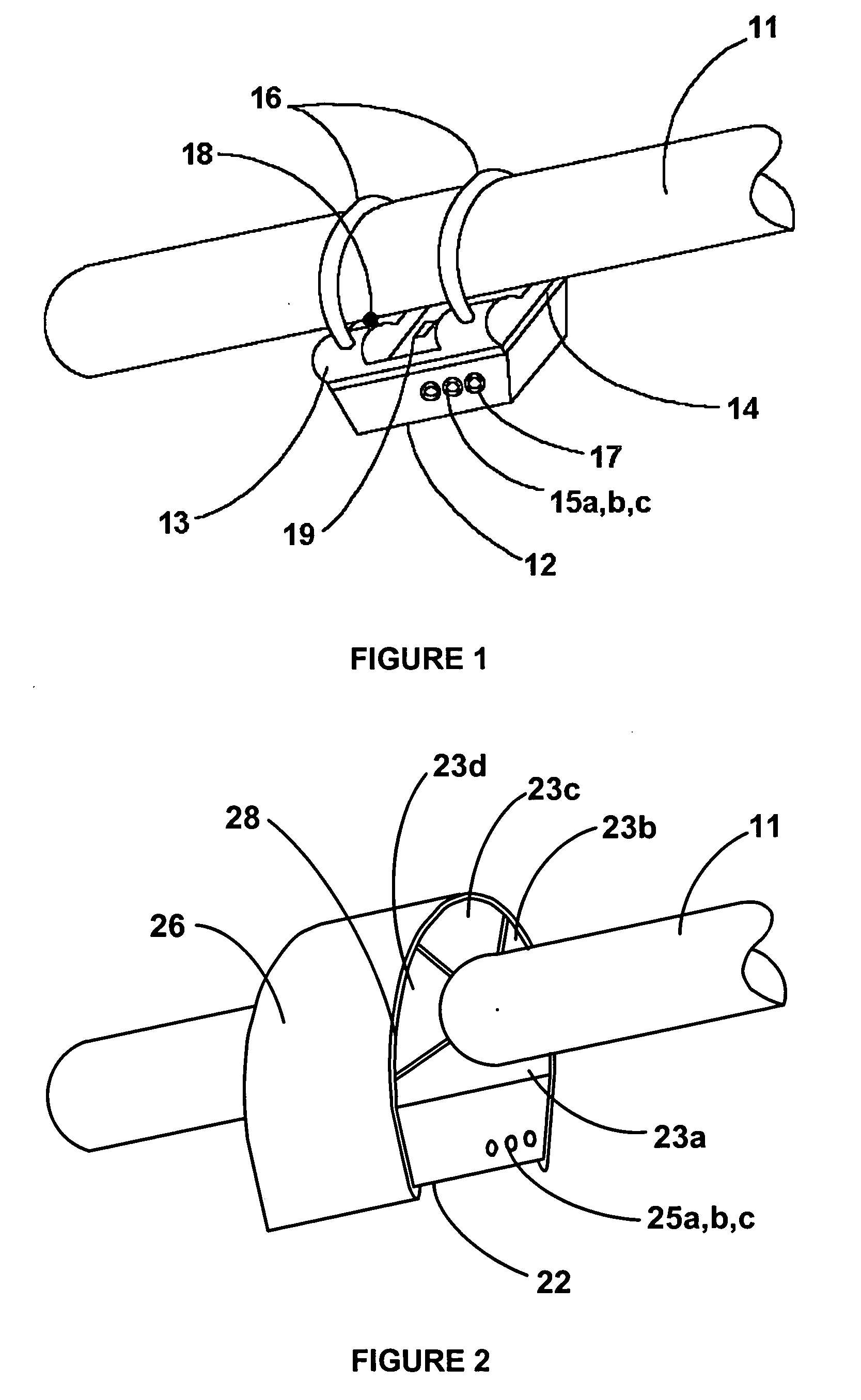
[0038] In one embodiment of the invention, the shot counter of the invention is mounted to the barrel of the firearm. Since it is preferable to measure the barrel temperature during firing, if the shot counter is to accumulate data on this parameter, it must have a thermal sensor be in thermal communication with the barrel. This is preferably done by having the shot counter itself mounted to the barrel.

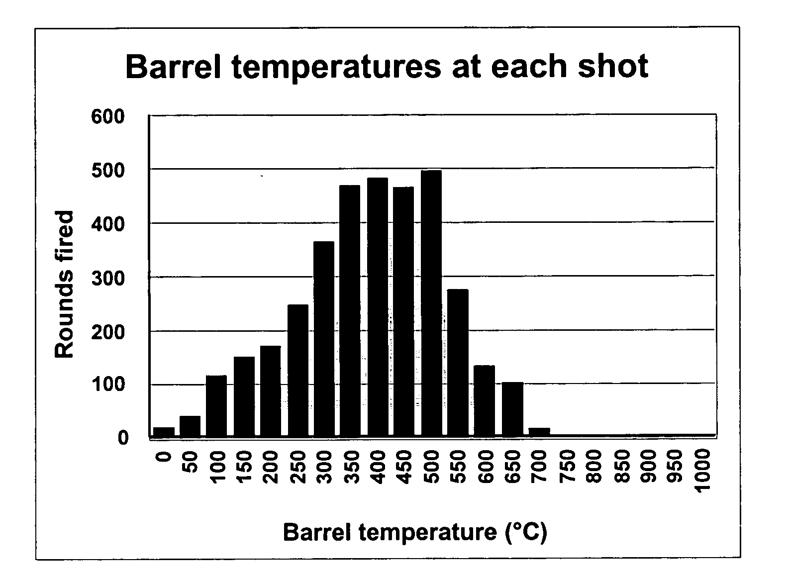
[0039] However, during heavy firing of an automatic weapon the gun barrel can reach temperatures of 400° C. or higher. Most commercial electronics are designed to operate at temperatures no higher than 125° C. and eutectic tin-lead solders melt at...

case 12

[0042] Case 12 may be attached to insulator 13 by any means that does not form an efficient thermal conduction path. A high-temperature silicone adhesive 14 is preferred as this class of material can withstand temperatures of over 400° C., has excellent adhesion to most materials and is resistant to attack by most common solvents. Useful alternate adhesives include cyano-acrylates and high-temperature epoxies. Mechanical fasteners with low thermal conductivity, for example ceramic or stainless steel machine screws, can also be used.

[0043] A thermocouple can be used as the temperature sensor. This may be embedded within the contact surface of insulator 13 with the bead 18 positioned so that it will contact the barrel 11. Alternatively a spring or compliant material can be used to maintain the thermocouple bead in contact with the barrel. If an infrared device 19 is used it is sufficient to provide a path for thermal radiation to reach the detector.

[0044] The shot counter case 12 is ...


PUM


Abstract

A system and method for collecting data on small-arms usage in the form of a device which is mounted to the firearm so as to be able to sense at least an impulse in the firearm due to firing. The device is mounted to the gun so as to detect impulses due to firing. A processor accepts impulse signals from the sensor, and uses either a hold-off delay or a windowing time to determine and store information related to the firing of the firearm. This information may be any combination of temperature, firing rate, firing intervals and time data for subsequent analysis, and, optionally, information identifying the weapon to which the device is attached. The device preferably has an interface to transfer data from the device to a computer or other data collection device.

Description

REFERENCE TO RELATED APPLICATION [0001] This is a continuation-in-part patent application of copending application Ser. No. 10 / 720,778, filed Nov. 24, 2003, entitled “A DEVICE FOR COLLECTING STATISTICAL DATA FOR MAINTENANCE OF SMALL-ARMS”, which is hereby incorporated herein by reference.BACKGROUND OF THE INVENTION [0002] 1. Field of the Invention [0003] This invention relates generally to the field of usage monitors for small-arms and more specifically to a device for determining wear in small-arms through data collection and statistical analysis. [0004] 2. Description of Related Art [0005] Many devices have been proposed to monitor the number of rounds fired an automatic or semi-automatic weapon. In general these devices are meant to warn the shooter before the magazine becomes empty. Some of these devices count the number of rounds in a magazine; others assume that a full magazine has been inserted and count the number of rounds fired using a shot detector. A few devices have bee...

Claims


Application Information

Patent Timeline
Patent Type & Authority Applications(United States)
IPC IPC(8): F41A19/01F41CG04F13/00G06F15/00
CPCF41A19/01
Inventor JOHNSON, ERIC ARTHURKULESZA, JOSEPH DUANEVANEVERY, ERIC
Owner ADVANCED DESIGN CONSULTING USA
Learn More