
Humidifier

Inactive Publication Date: 2005-05-26
NISSAN MOTOR CO LTD +1
View PDF5 Cites 42 Cited by
  • Summary
  • Abstract
  • Description
  • Claims
  • Application Information

AI Technical Summary

Benefits of technology

[0007] In the conventional humidifier, the pitches between the vent holes are equal to each other, distances between the vent holes is different. When the distances between the vent holes are different, a compression force and a tensile stress applied in the axial direction of the vent pipe are varied, there is an adverse possibility that the vent pipe is buckled or deformed between the vent holes. When the vent pipe is buckled or deformed between the vent holes, gas is leaked or gas is unevenly distributed, the hollow-fiber membrane is damaged, the humidifying performance of the humidifier is largely deteriorated, and the lifetime of the humidifier is shortened.

Problems solved by technology

When the distances between the vent holes are different, a compression force and a tensile stress applied in the axial direction of the vent pipe are varied, there is an adverse possibility that the vent pipe is buckled or deformed between the vent holes.
When the vent pipe is buckled or deformed between the vent holes, gas is leaked or gas is unevenly distributed, the hollow-fiber membrane is damaged, the humidifying performance of the humidifier is largely deteriorated, and the lifetime of the humidifier is shortened.
It is difficult to form vent holes having various opening areas in the vent pipe, and the producing method of the vent pipe is complicated in a designing point of view.

Method used


Image

  • Humidifier
  • Humidifier
  • Humidifier

Examples


first embodiment

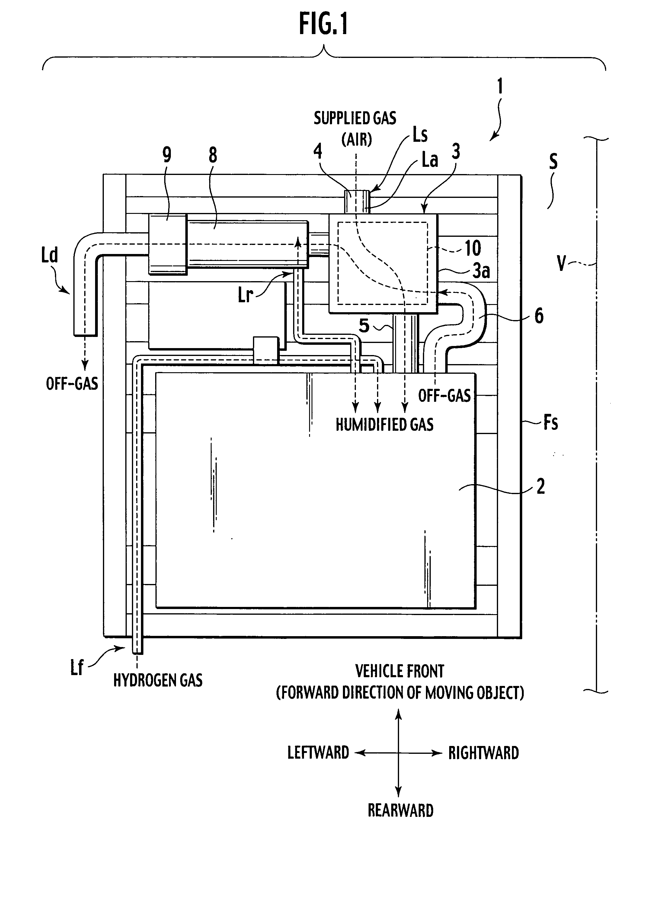
[0017] In the first embodiment, a humidifier disposed in a fuel cell system mounted in a fuel cell vehicle will be explained based on FIGS. 1 to 5.

[0018]FIG. 1 is a block diagram showing a portion of the fuel cell system disposed below a floor of a fuel cell automobile.

[0019] As shown in FIG. 1, a fuel cell system 1 includes a fuel cell 2, a utility supply system (Ls), support frames (Fs), and an off-gas processing system.

[0020] The utility supply system (Ls) includes a fuel supply system and an oxidizer supply system. The fuel supply system includes a fuel supply line (Lf) supplying fuel to the fuel cell 2. The oxidizer supply system includes an oxidizer supply line (La) supplying oxidizer gas (air) to the fuel cell 2.

[0021] A humidifier 3 is disposed in the oxidizer supply line La of the fuel cell system 1. The humidifier 3 is connected to a gas inlet pipe 4 connected to a compressor (not shown) and to a gas outlet pipe 5 connected to the fuel cell 2.

[0022] The off-gas proces...

second embodiment

[0034] In the second embodiment, the humidifier 1 of the first embodiment is improved in order to prevent the fiber of the hollow-fiber membrane from being cut. This humidifier will be explained.

[0035]FIG. 6 is a side view showing a structure of a hollow-fiber membrane module in the humidifier of the second embodiment. Substantially the same elements as those shown in FIG. 5 of the first embodiment are designated with like reference numerals, and explanation thereof is omitted. As shown in FIG. 6, in the hollow-fiber membrane module 23 of the second embodiment, no vent hole is formed directly below and around the gas conduit 17. Vent holes 15d and 15e are formed only at positions away from the gas conduit 17. No vent hole is formed directly below and around the gas conduit 21. Vent holes 19d and 19e are formed only at positions away from the gas conduit 21.

[0036] According to the hollow-fiber membrane module 23, the distances from the gas conduit 17 and the vent holes 15d and 15e ...


PUM

PropertyMeasurementUnit
Lengthaaaaaaaaaa
Widthaaaaaaaaaa
Permeabilityaaaaaaaaaa

Abstract

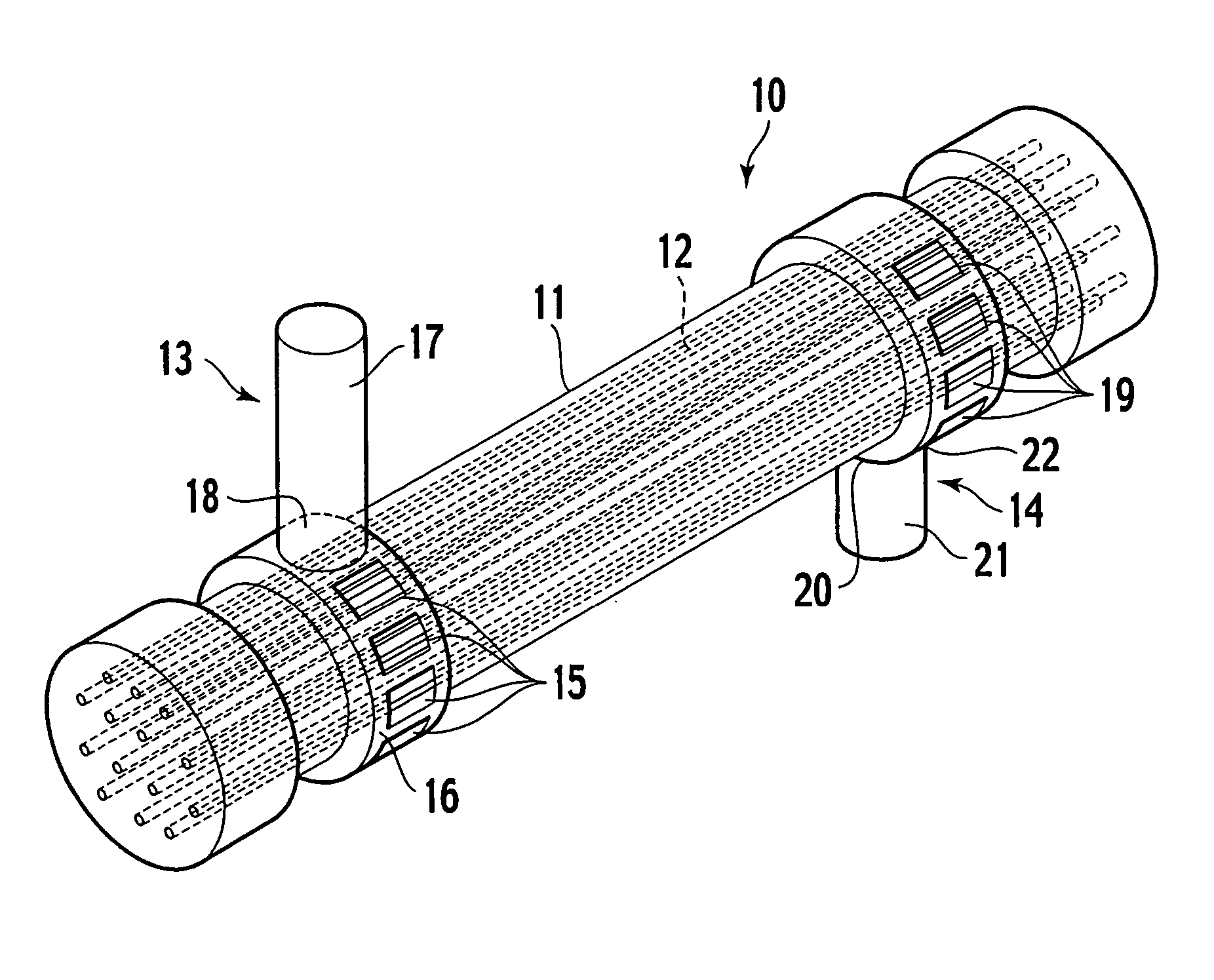
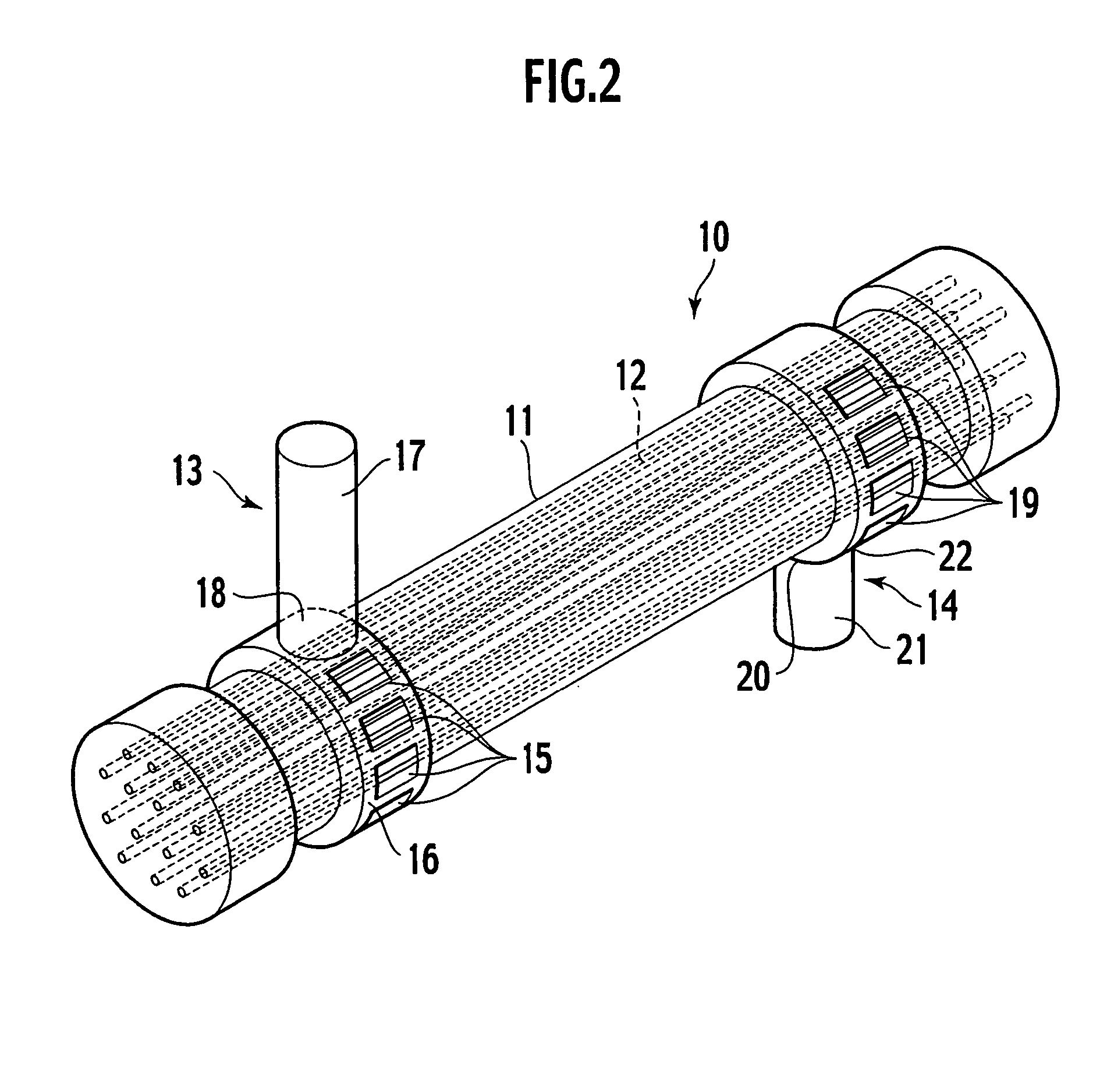
A humidifier has a hollow-fiber membrane module comprising a cylindrical gas vent pipe, a permeable hollow-fiber membrane accommodated in the vent pipe, and a first distributing mechanism disposed in the vent pipe. The first distributing mechanism includes a plurality of vent holes formed along an outer periphery of the vent pipe, a distributor covering the vent holes, a gas conduit communicating with the distributor, and a connection hole connecting the gas conduit and the vent holes to each other. Widths of the vent holes in a circumferential direction of the vent pipe are equal to each other, and quantities of flow of gas flowing from the vent holes are equal to each other.

Description

BACKGROUND OF THE INVENTION [0001] 1. Technical field [0002] The present invention relates to a humidifier provided in an air supply line supplying air to a fuel cell. [0003] 2. Related art [0004] A fuel cell uses hydrogen gas as a fuel and allows hydrogen gas and oxygen gas to react with each other to generate electricity. The fuel cell receives attention in view of global environmental protection because exhaust gas is not generated for generating electricity. In recent years, attempts have been made to put the fuel cell to practical use as a power source of an automobile. [0005] A vehicle such as an automobile mounts a fuel cell system including the fuel cell. An air supply line supplying air including oxygen gas is connected to the fuel cell, and a humidifier is disposed on the air supply line. The humidifier collects moisture contained in off-gas discharged from the fuel cell, air is humidified using the collected moisture, and the humidified air is supplied to the fuel cell. [...

Claims


Application Information

Patent Timeline
IPC IPC(8): B01D63/02F24F6/04B01F3/04H01M8/04H01M8/10
CPCB01D63/02H01M8/04126H01M2250/20Y02T90/32B01D2313/26Y02E60/50B01D2313/105Y02T90/40
Inventor TANAKA, SHIROINAMURA, TAMIO
Owner NISSAN MOTOR CO LTD
Learn More