
Method and system of evaporative emission control for hybrid vehicle using activated carbon fibers

a technology of activated carbon fiber and hybrid vehicles, applied in the direction of condensed fuel collection/return, charge feed system, non-fuel substance addition to fuel, etc., can solve the problems of vapor breakthrough, hydrocarbon emissions, and the near shutdown of the internal combustion engine, and achieve the effect of reducing pressure drop through the scrubber

Active Publication Date: 2005-05-26
GM GLOBAL TECH OPERATIONS LLC
View PDF8 Cites 33 Cited by
  • Summary
  • Abstract
  • Description
  • Claims
  • Application Information

AI Technical Summary

Benefits of technology

[0009] In still other features, the evaporative emissions control system for a hybrid vehicle uses activated carbon granules that may be derived from wood and activated carbon fiber material derived from phenolic fibers, particularly novoloid fibers. The activated carbon fiber material may be in the form of an activated carbon fiber felt or mat, and may be rolled with a sheet of coarse foam (e.g., urethane foam) to reduce pressure drop through the scrubber. In certain embodiments, the evaporative control system may reduce bleed emissions to below 3 mg / day, particularly below 2.0 mg / day.

Problems solved by technology

One problem encountered by such a system has been vapor breakthrough, or hydrocarbon emissions from the vented vapor adsorption canister, which is often referred to as canister bleed emissions.
In a hybrid vehicle, however, the internal combustion engine is turned off nearly half of the time during vehicle operation.
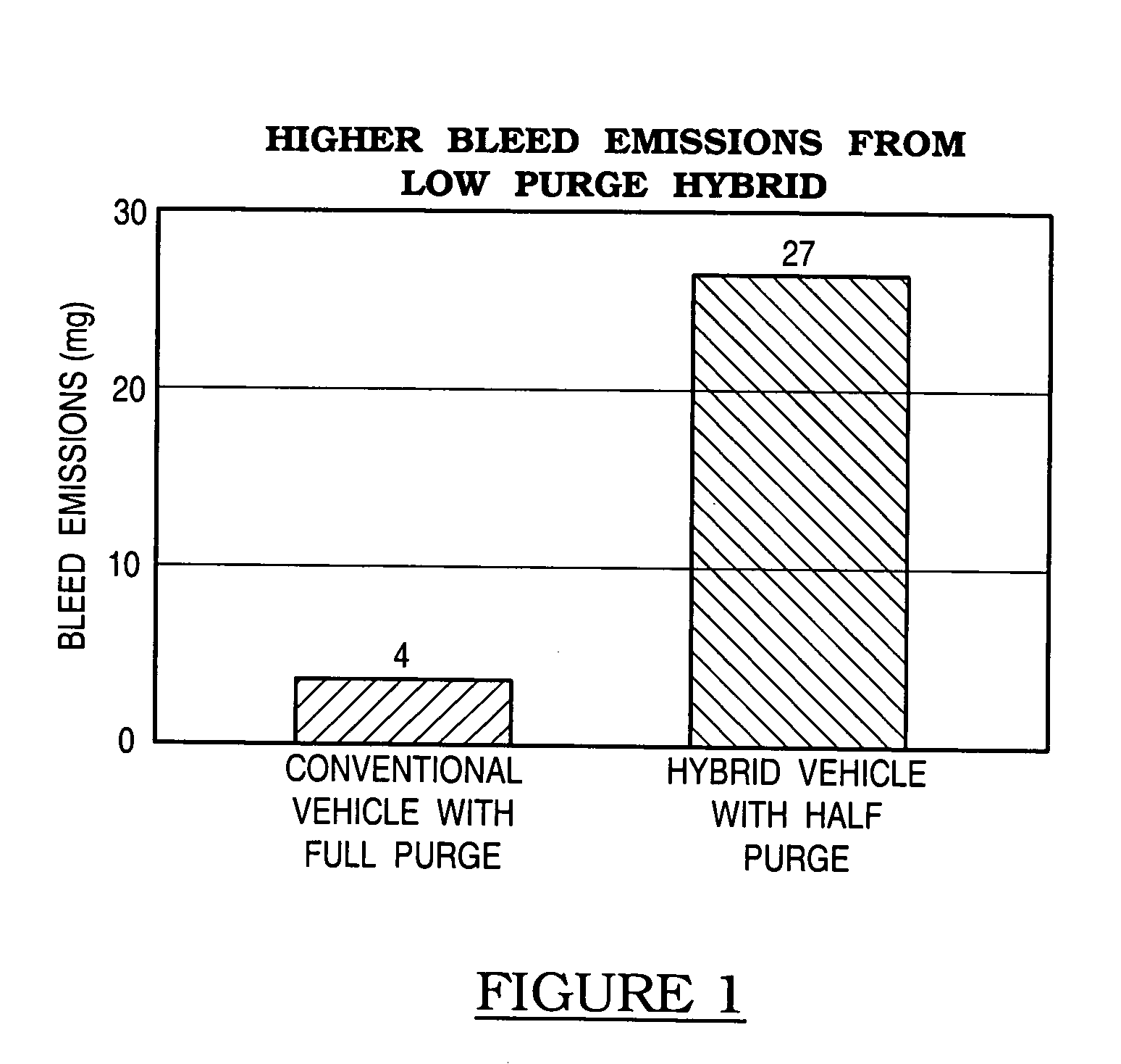
A hybrid vehicle generates nearly the same amount of evaporative fuel vapor as does a conventional vehicle, however, with the result that the lower purge rate of the hybrid vehicle is not sufficient to clean the adsorbed fuel out of the evap canister, resulting in higher evaporative bleed or breakthrough emissions. FIG. 1 demonstrates the difference in bleed emissions, using air purging in a conventional vehicle with only an internal combustion engine and in a hybrid vehicle.

Method used


Image

  • Method and system of evaporative emission control for hybrid vehicle using activated carbon fibers
  • Method and system of evaporative emission control for hybrid vehicle using activated carbon fibers
  • Method and system of evaporative emission control for hybrid vehicle using activated carbon fibers

Examples


Embodiment Construction

[0024] The following description of the preferred embodiment(s) is merely exemplary in nature and is in no way intended to limit the invention, its application, or uses.

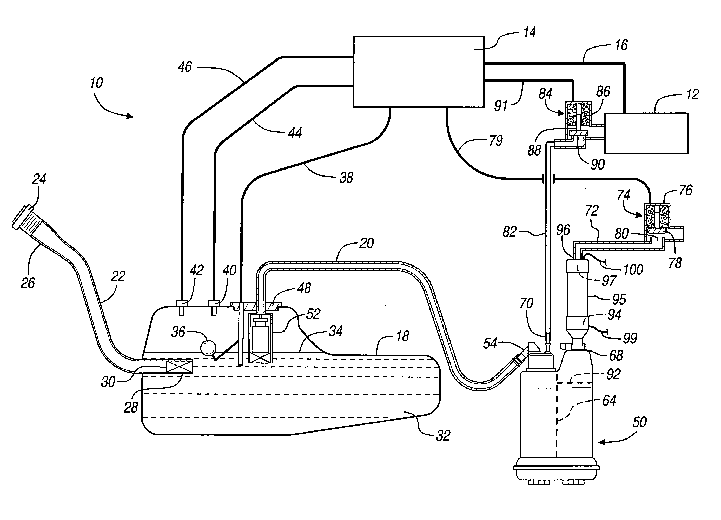
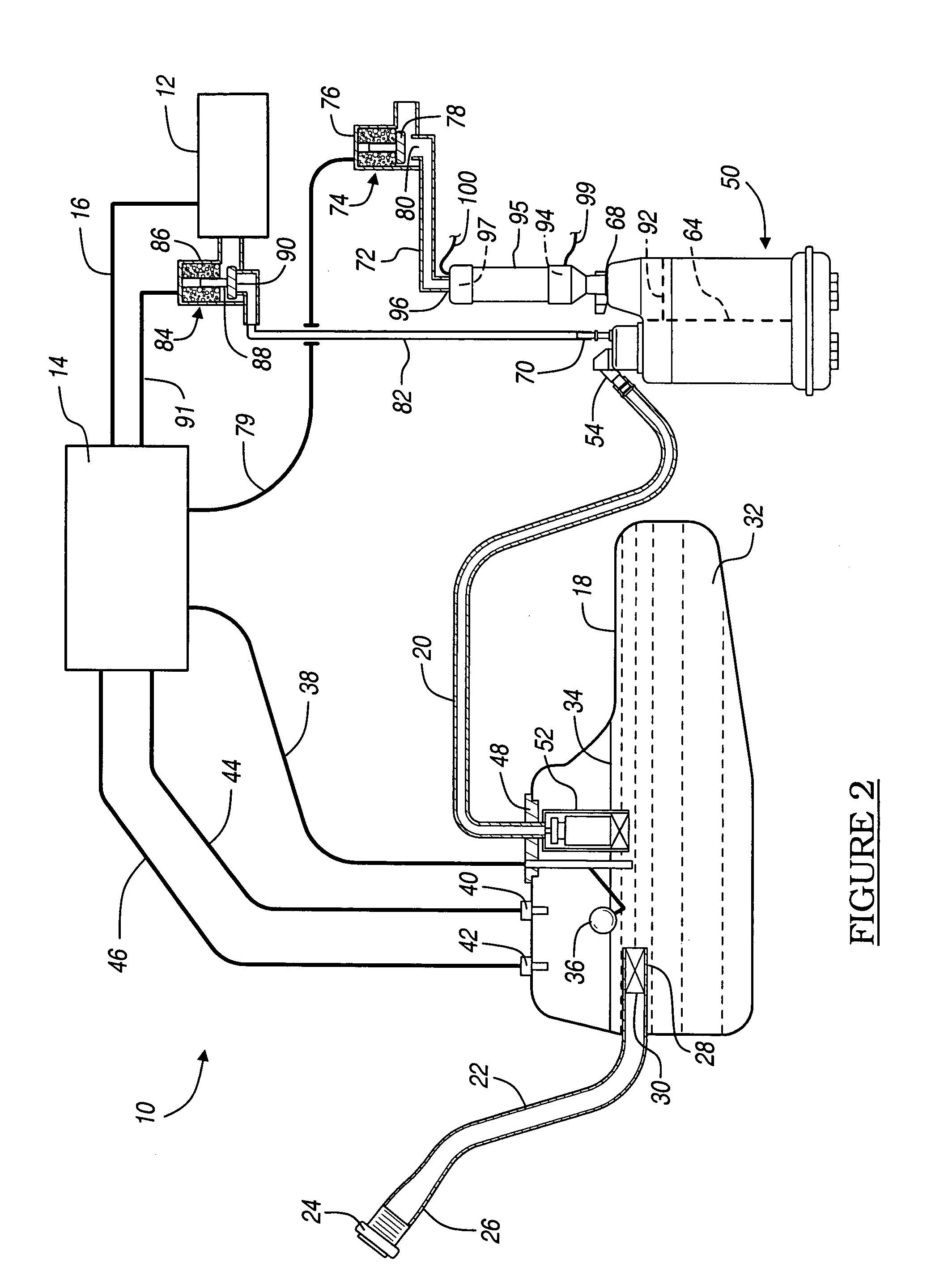
[0025] Referring now to FIGS. 2 and 3, an evaporative control system 10 for a hybrid vehicle including an internal combustion engine 12 and an electric motor (not shown) is illustrated. Hybrid vehicles combine a gasoline fueled internal combustion (IC) engine and an electric motor to provide a hybrid powertrain with improved fuel economy. Frequent on-off engine operation results in much smaller canister purge air volume. Because the IC engine does not operate nearly 50% of the time, canister purging with fresh air occurs less than 50% of the time during vehicle operation. The internal combustion engine 12 is preferably controlled by a controller 14. The engine 12 typically burns gasoline, ethanol, and other volatile hydrocarbon-based fuels. The controller 14 may be a separate controller or may form part of an engine...


PUM


Abstract

An evaporative emission control system for a hybrid vehicle comprises a scrubber containing an activated carbon fiber material selected to adsorb butane and / or pentane isomer vapors in low concentrations in air passing through the scrubber and apparatus for resistive heating of the activated carbon fiber material to help desorb the adsorbed butane and / or pentane isomers during a period when the internal combustion engine is operating for combustion of the desorbed vapor in the engine. The fibers are conductive and heat by resistive heating when electric current is passed through the fibers by the apparatus.

Description

FIELD OF THE INVENTION [0001] The present invention relates to methods and systems for evaporative emission control for hybrid vehicles, and more specifically to methods and systems for reducing and preventing vapor emissions from fuel tanks of such vehicles. BACKGROUND OF THE INVENTION [0002] Gasoline typically includes a mixture of hydrocarbons ranging from higher volatility butanes (C4) to lower volatility C8 to C10 hydrocarbons. When vapor pressure increases in the fuel tank due to conditions such as higher ambient temperature or displacement of vapor during filling of the tank, fuel vapor flows through openings in the fuel tank. To prevent fuel vapor loss into the atmosphere, the fuel tank is vented into a canister that contains an adsorbent material such as activated carbon granules (“evap” canister). [0003] The fuel vapor is a mixture of the gasoline vapor (referred to in this description also by its main component, hydrocarbon vapor) and air. As the fuel vapor enters an inle...

Claims


Application Information

Patent Timeline
Patent Type & Authority Applications(United States)
IPC IPC(8): F02M25/08
CPCF02M25/0836
Inventor REDDY, SAM R.
Owner GM GLOBAL TECH OPERATIONS LLC
Learn More