
Particulate deposit avoidance and probe positioning

Inactive Publication Date: 2005-05-26
AVL TEST SYST
View PDF16 Cites 4 Cited by
  • Summary
  • Abstract
  • Description
  • Claims
  • Application Information

AI Technical Summary

Benefits of technology

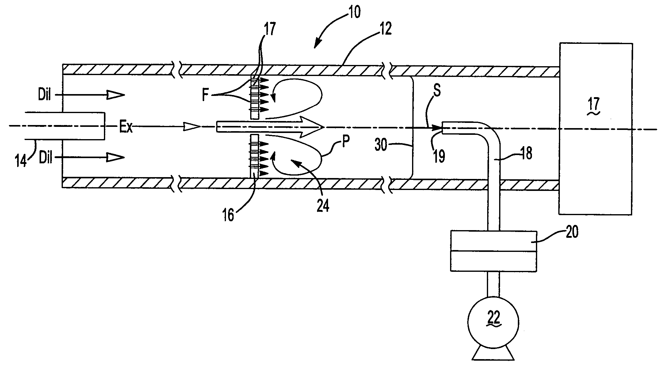
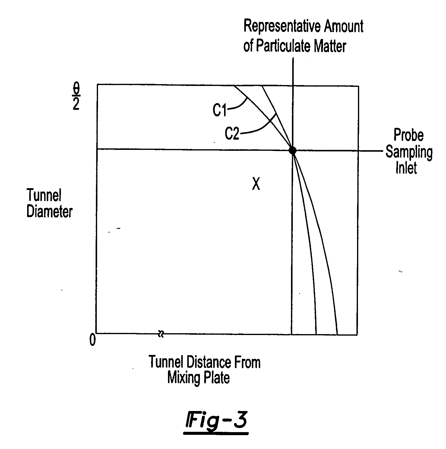
[0006] The example system also includes a probe that is arranged in the dilution tunnel downstream from the mixing plate for receiving the sample mixture. The sampler includes a filter having a filter element for collecting particulate matter. An inlet of the probe is offset from a centerline of the dilution tunnel by a predetermined amount corresponding to an average particulate concentration location along a profile of the sample mixture to reduce the tunnel length.
[0008] Accordingly, the present invention provides a shorter dilution tunnel having which is configured in such a way to prevent the deposit of particulate matter on the surfaces of the dilution tunnel.

Problems solved by technology

Prior art exhaust sampling system using tunnels have two significant problems.
First, particulate matter is deposited on portions of the dilution tunnel causing inaccuracies in the results since this particulate matter is never sampled or collected on the filter media and measured.
Particulate matter carried in the mixture is deposited on walls in the stagnant area, which results in this particulate matter not being collected by the filter resulting in inaccuracies.
However, this arrangement did not prevent particulate matter from collecting on the surfaces of the dilution tunnel.
Second, prior art tunnels are significantly long and difficult to package.

Method used


Image

  • Particulate deposit avoidance and probe positioning
  • Particulate deposit avoidance and probe positioning
  • Particulate deposit avoidance and probe positioning

Examples


Embodiment Construction

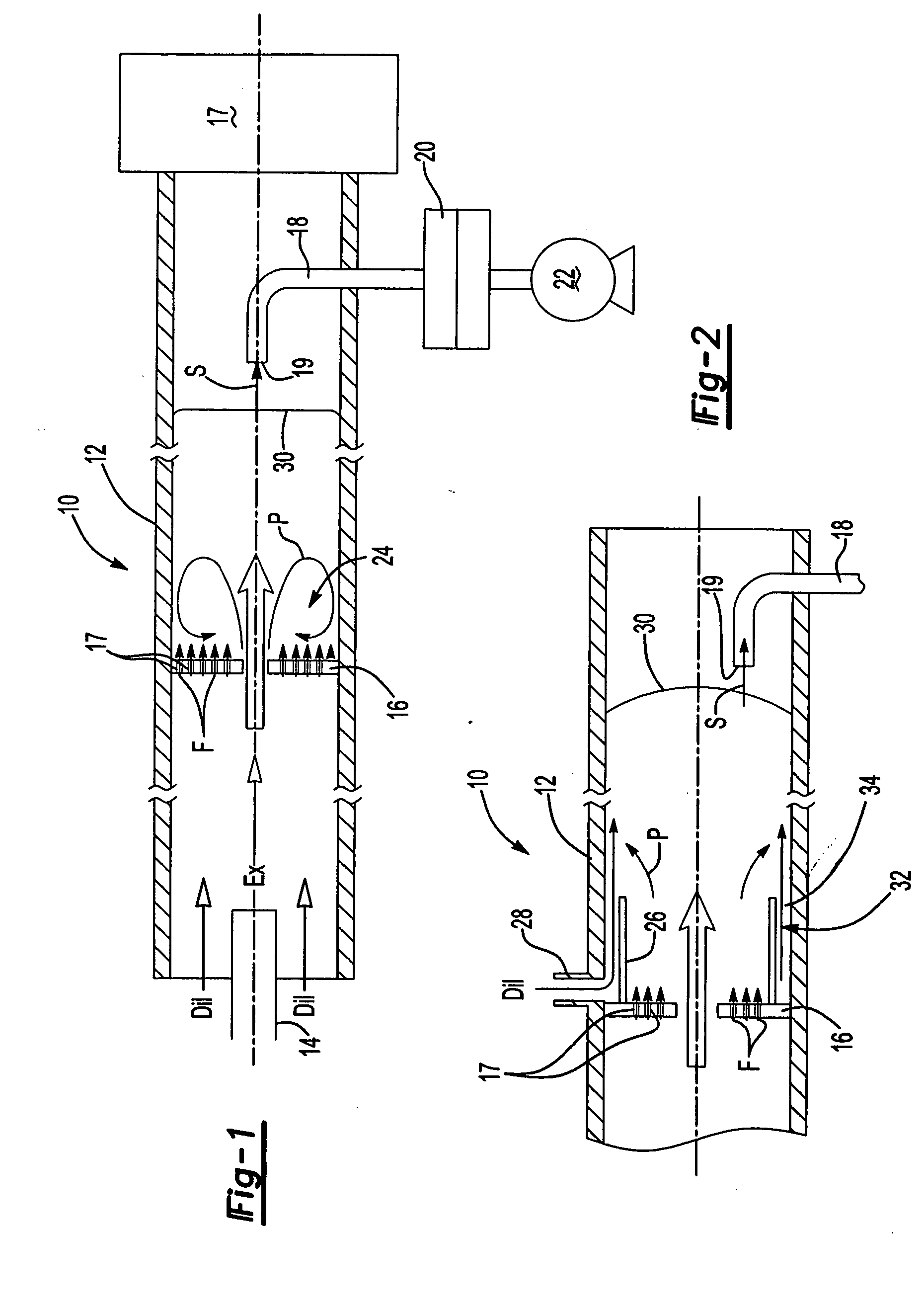
[0012] An inventive exhaust sampling system 10 is shown in FIG. 1. The system 10 includes a dilution tunnel 12 carrying exhaust gas from an exhaust source 14, such as a tailpipe of a vehicle. Dilution air is also present in the dilution tunnel 12 and is mixed with the exhaust gas by an orifice in a mixing plate 16. The dilution gas may be atmospheric air or another fluid. The exhaust gas and dilution gas mixes along the length of the dilution tunnel 12 to provide a sample mixture.

[0013] Once the gases are homogeneously mixed a sampling probe 18 having an inlet 19 samples a portion of the mixture for subsequent analysis. The sample S taken by the probe 18 may go through a filter 20, which traps particulate matter found in the sample S. A pump 22 is used to pull the sample through the sampling probe 18. A device 17 pulls the mixture through the dilution tunnel and may also include various flow measurement devices, transducers, and other components found in exhaust sampling system. Th...


PUM


Abstract

A perforated mixing plate and is fluid passage are used in conjunction with a dilution tunnel to prevent particulate matter from collecting on the sampling system components. An inlet of a sampling probe is offset from the centerline of the dilution tunnel to a location corresponding to an average particulate matter concentration along a flow profile of a sample mixture to reduce the length of the dilution tunnel.

Description

BACKGROUND OF THE INVENTION [0001] This application claims priority to provisional application Ser. No. 60 / 515,733 filed Oct. 30, 2003.[0002] The invention relates to an exhaust sampling system having a dilution tunnel. Prior art exhaust sampling system using tunnels have two significant problems. First, particulate matter is deposited on portions of the dilution tunnel causing inaccuracies in the results since this particulate matter is never sampled or collected on the filter media and measured. Prior art dilution tunnels having mixing plates that are prone to stagnant areas in which the turbulent flow of exhaust and dilution gases through the orifice recirculate and collect on the surface of the mixing plate near the orifice. Particulate matter carried in the mixture is deposited on walls in the stagnant area, which results in this particulate matter not being collected by the filter resulting in inaccuracies. One proposed solution was to provide a fluid chamber arranged outside ...

Claims


Application Information

Patent Timeline
IPC IPC(8): G01N1/22G01N15/06
CPCG01N1/2205G01N1/2252G01N2001/2264G01N2001/225G01N15/0618
Inventor KREFT, NORBERT
Owner AVL TEST SYST
Learn More