Steam blower box

a blower box and steam technology, applied in the field of steam blower boxes, can solve the problems of reducing the structural width of the steam blower box, preventing air entry and attendant turbulence, and only achieving ideal conditions for maximum efficiency of steam application,

Inactive Publication Date: 2005-05-26
V I B SYST
View PDF8 Cites 0 Cited by
  • Summary
  • Abstract
  • Description
  • Claims
  • Application Information

AI Technical Summary

Benefits of technology

[0017] In accordance with a further development, a group of openings is arranged in such a way that it directly borders on an adjacent group over a portion of its length in the web travel direction. This makes it possible to reduce the structural width of the steam blower box.
[0018] As is the case in the first embodiment, separate channels are formed so that the air is deflected in a controlled manner in a certain direction. Turbulences are substantially prevented.
[0019] It is also advantageous to provide at least one area without steam outlet openings within a group of openings.
[0020] In accordance with a further development of the invention, the borders of the respective groups are formed by continuous rows of steam outlet openings, so that the entry of air and the attendant turbulences are prevented.

Problems solved by technology

However, a maximum efficiency of the steam application is only achieved under ideal conditions, i.e., if no additional heat transfer resistance between the steam and the web is present.
This ideal condition is practically never achieved.
However, the steam application space at a running web is normally not only filled with steam.
A portion of the steam condenses in the air instead of at the web and, therefore, can no longer contribute to the desired heating and moisture enrichment of the web.
In addition, the air which is heated and enriched with water becomes oversaturated during cooling and precipitates water droplets.
The resulting water vapors negatively affect the climate within the work area and results in the formation of droplets at machine components.
Accordingly, the principal disadvantage of the presence of air is the reduced efficiency of the steam application.
Also, it is frequently necessary to suction off this excess steam, wherein a high suction power is required, on the one hand, and, on the other hand, there is the danger that an unintentional suctioning off of steam portions will reduce the efficiency of the steam application.

Method used


Image

  • Steam blower box
  • Steam blower box
  • Steam blower box

Examples


Embodiment Construction

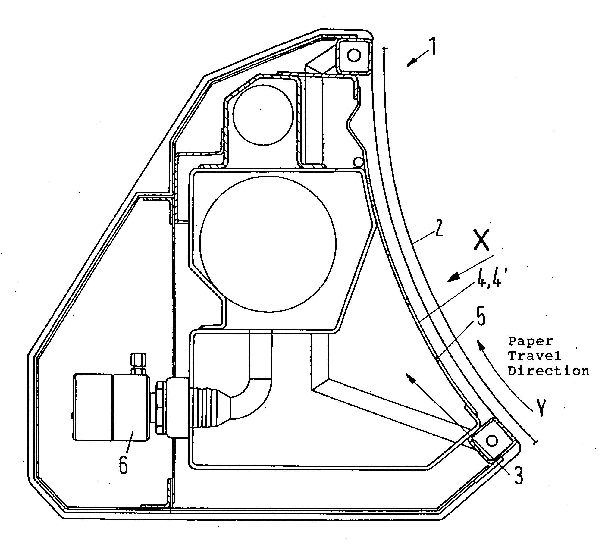
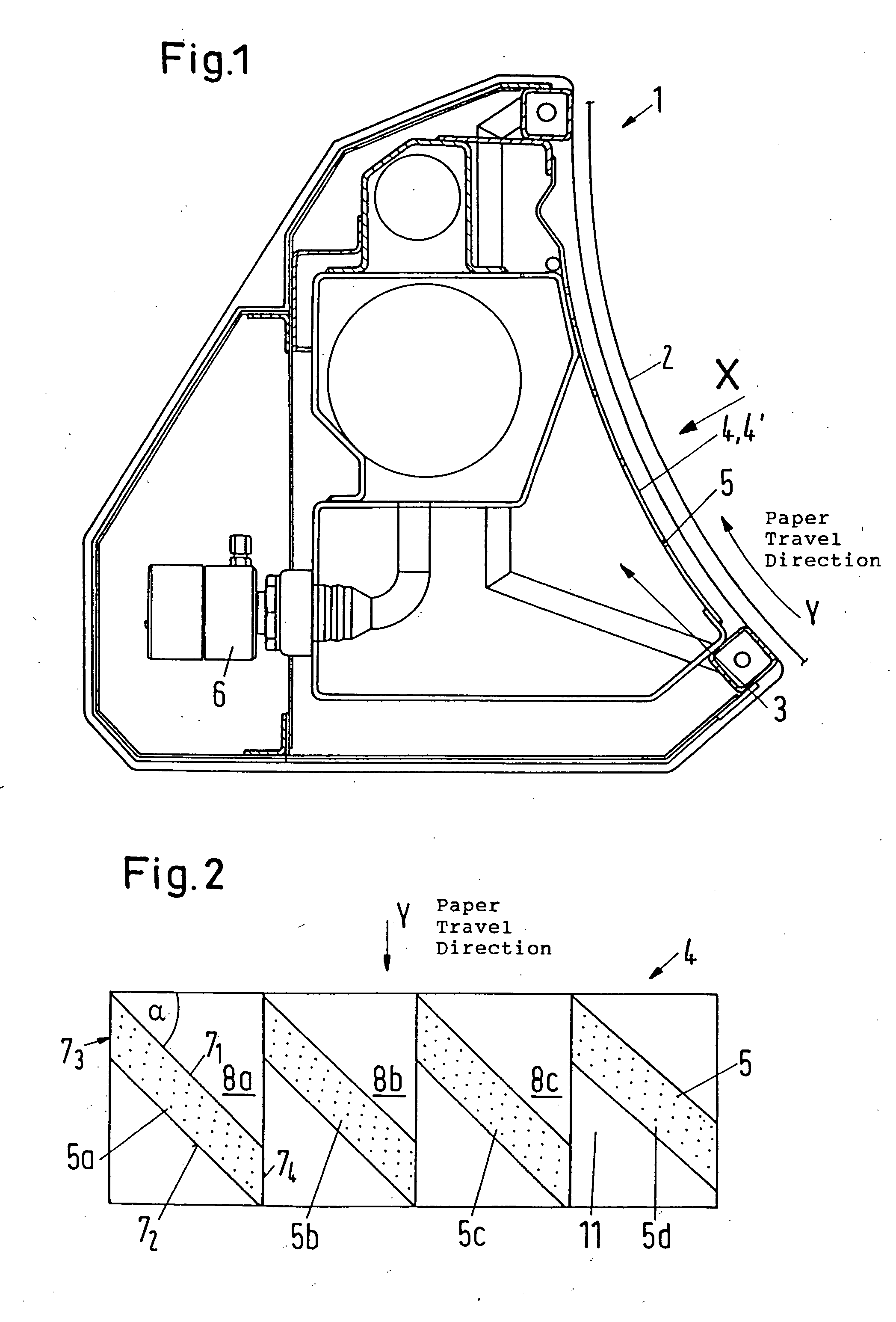
[0031] A steam blower box 1 is used, for example, for the steam application onto a material web, particularly a paper web 2, at a calendar, not shown. The paper web travels through one or more roll nips for improving the gloss and smoothness properties of the web. The web 2 is conveyed along the steam blower box 1 in the direction of the arrow Y and steam is applied to the web.

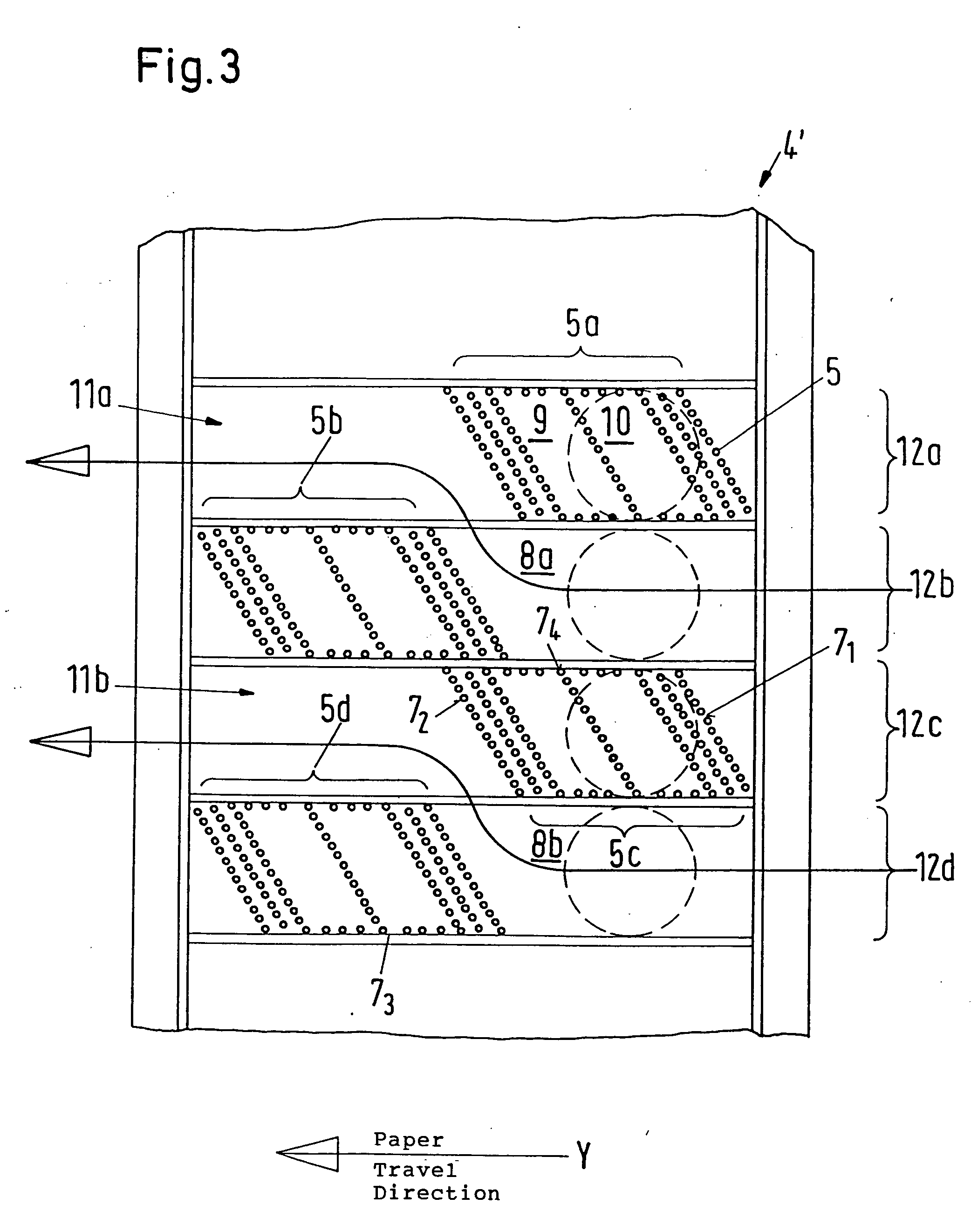
[0032] The steam blower box 1 has a steam blower chamber 3 with a housing wall 4 facing the paper web 2, wherein a plurality of steam outlet openings 5 are provided in the housing wall 4. Steam is supplied through the steam blower chamber 3 through a steam valve 6 and the steam is ejected through the steam outlet openings 5 onto the paper web 2 where the steam condensates and the temperature and the moisture of the paper web 2 is increased prior to the processing in the roll nip of the calendar. To the extent described so far, the steam blower box 1 does not differ from conventional steam blower boxes as desc...


PUM


Abstract

A steam blower box for the application of steam on a material web, particularly paper, which travels past the steam blower box includes a housing wall which faces the material web and extends transversely of the web travel direction. A plurality of steam outlet openings are arranged in the housing wall. The steam outlet openings are arranged in at least two separate groups, wherein at least one section which is free of steam application is provided between two adjacent groups, and wherein the air entrained by the material web is discharged through this section.

Description

BACKGROUND OF THE INVENTION [0001] 1. Field of the Invention [0002] The present invention relates to a steam blower box for the application of steam on a material web, particularly paper, which travels past the steam blower box. The steam blower box includes a housing wall which faces the material web and extends transversely of the web travel direction, wherein a plurality of steam outlet openings are arranged in the housing wall. [0003] 2. Description of the Related Art [0004] In the manufacture of paper or the further processing of paper, steam is frequently admitted to the running web. There are various reasons for this application of steam. However, the object is always to condensate the steam emitted from the steam blower box as precisely as possible on or in a certain area of the web, and to transfer heat and / or moisture to the web in this manner. Differing quantities of condensation transversely of the web make it possible to influence certain properties, such as gloss, smoo...

Claims


Application Information

Patent Timeline
Patent Type & Authority Applications(United States)
IPC IPC(8): D21F7/00
CPCD21F7/008
Inventor WINHEIM, STEFAN
Owner V I B SYST
Why Eureka
Try Eureka