Switching arrangement for low-voltage circuit breakers

A technology of low-voltage circuit breaker and switchgear, which is applied in the direction of high-voltage air circuit breaker, high-voltage/high-current switch, electric switch, etc., and can solve the problems of large bending stress of supporting pins

Inactive Publication Date: 2005-12-07
SIEMENS AG
View PDF2 Cites 0 Cited by
  • Summary
  • Abstract
  • Description
  • Claims
  • Application Information

AI Technical Summary

Problems solved by technology

[0004] All of these devices have the disadvantage that the bending stresses of the bearing pins of the movable contact rod are particularly high, since the force of the contact rod is mainly concentrated in the center

Method used


Image

  • Switching arrangement for low-voltage circuit breakers
  • Switching arrangement for low-voltage circuit breakers
  • Switching arrangement for low-voltage circuit breakers

Examples


Embodiment Construction

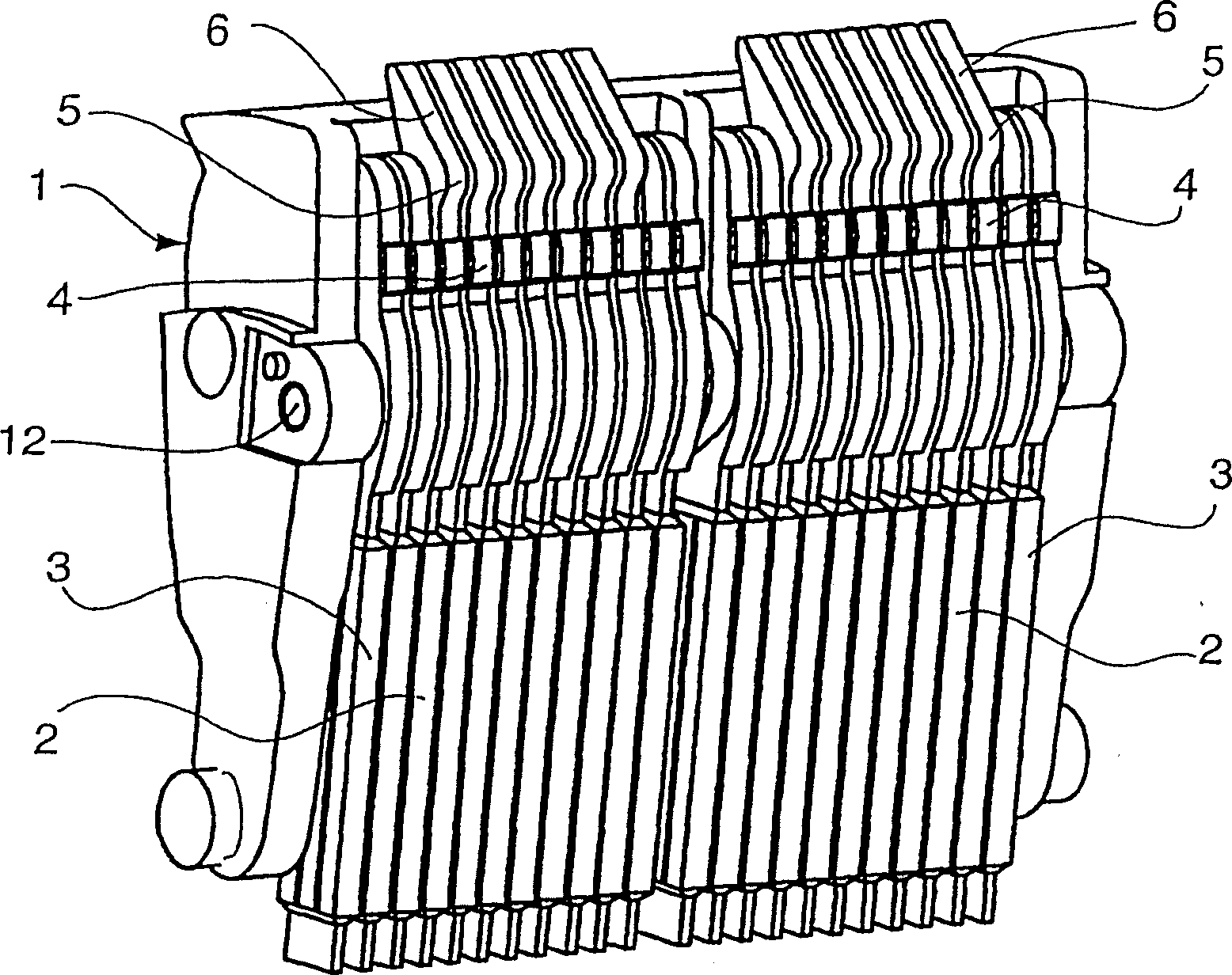
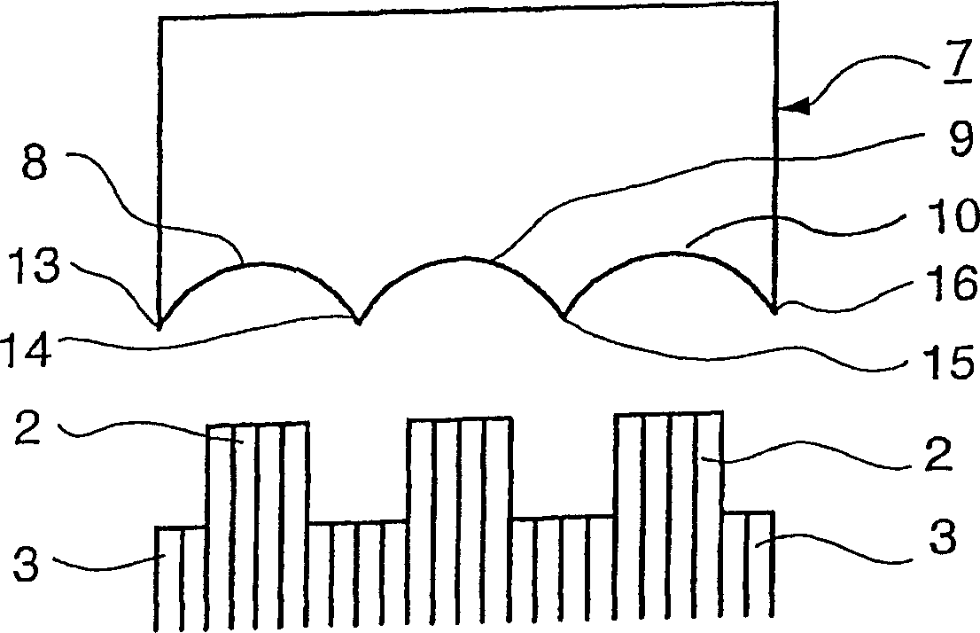
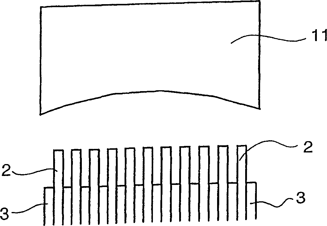
[0016] figure 1 A movable contact carrier 1 with multiple contacts for a low-voltage circuit breaker with a high rated current is shown, which has a plurality of movable contact rods 2 , 3 which are arranged parallel to one another at a small relative distance. In this case, a part of the contact rod 2 has, in addition to the main contact 4 , a preliminary contact 5 which is arranged between the end of the contact rod 2 designed as an arc 6 and the main contact 4 . These movable precontact contacts 5 , like the movable main contacts 4 , cooperate in a known manner with non-illustrated fixed precontact contacts and main contacts. According to the invention, the contact rods 3 which are not provided with pre-contact contacts 5 are arranged in a defined sequence which differs from the conventional arrangement which is limited to the outer area, here they are arranged in sections or in groups. The arrangement sequence is not limited to the one shown in the present embodiment, in...


PUM


Abstract

A switching arrangement for low-voltage circuit breakers with a high nominal current, comprising moveable switching contacts (2,3) arranged essentially on a moveable contact carrier (1), fixed switching contacts and a device for cooling, de-ionizing and extinguishing an electric switching arc (7, 11). The fixed contact is provided with a pre-contact function over the entire contact width thereof. Moveable contact levers (2,3) are arranged according to a set pattern in a distributed manner over the entire width of the contact carriers and are provided with or without a pre-contact (5). A contact lever (2) with a pre-contact (5) and a contact lever (3) without a pre-contact can be provided successively. Similarly, two or more contact levers (2) with a pre-contact (5) and two or more contact levers (3) without a pre-contact can be successively and alternatingly provided in packet-form.

Description

technical field [0001] The invention relates to a switching device for a low-voltage circuit breaker with a large rated current, which mainly includes movable switching contacts arranged on a movable contact bracket, fixed switching contacts and a A device for cooling, deionizing and extinguishing switching arcs. Background technique [0002] Low-voltage circuit breakers with high rated currents have contact systems with wide structural dimensions determined by their function. This depends on the continuous current of the switch and not on its breaking capacity, which is generally the same for all switches (independent of their rated current) and is designed for a maximum of approximately 100 kA. The cross section of the busbar, ie the width of the busbar and the contact system, is therefore determined for the continuous current. In such contact systems, the movable contacts are designed as multiple contact systems with a defined number of identical contact rods. These co...

Claims


Application Information

Patent Timeline
Patent Type & Authority Patents(China)
IPC IPC(8): H01H33/12H01H1/22H01H33/14
CPCH01H1/226
Inventor 冈特·塞德勒德特莱夫·施米特塞蔡·图尔克曼迈克尔·塞贝科迈克尔·巴赫英戈·蒂德
Owner SIEMENS AG
Why Eureka
Try Eureka