
Orthopaedic spacer

a prosthetic system and orthopaedic technology, applied in the field of orthopaedic spacers and prosthetic systems, can solve the problems of affecting the quality of life of the prosthesis, the distraction of native bone ends, and so as to facilitate and quickly connect or disassemble, minimize the damage to the soft tissue, and minimize the effect of damag

Inactive Publication Date: 2005-05-19
DEPUY PROD INC
View PDF53 Cites 27 Cited by
  • Summary
  • Abstract
  • Description
  • Claims
  • Application Information

AI Technical Summary

Benefits of technology

[0007] The present invention addresses the need for orthopaedic components, such as trials and implants, that offer flexibility, that can be easily and quickly assembled or connected and disassembled or disconnected, and that can be temporarily inserted or implanted while minimizing damage to the soft tissue at the remaining portions of native bone.

Problems solved by technology

Severe trauma and disease can lead to significant amounts of bone loss.
However, it may be difficult to implant such a mid-shaft prosthesis.
Since the native bone ends are surrounded by and connected to soft tissue, distraction of the native bone ends can damage the soft tissue and the connections between the soft tissue and the native bone ends.
However, as described above with respect to intercalary implants, it may be difficult to insert such a mid-shaft trial without damaging the soft tissue at the native bone ends.

Method used


Image

  • Orthopaedic spacer
  • Orthopaedic spacer
  • Orthopaedic spacer

Examples


Embodiment Construction

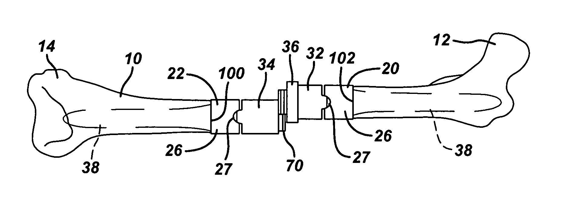
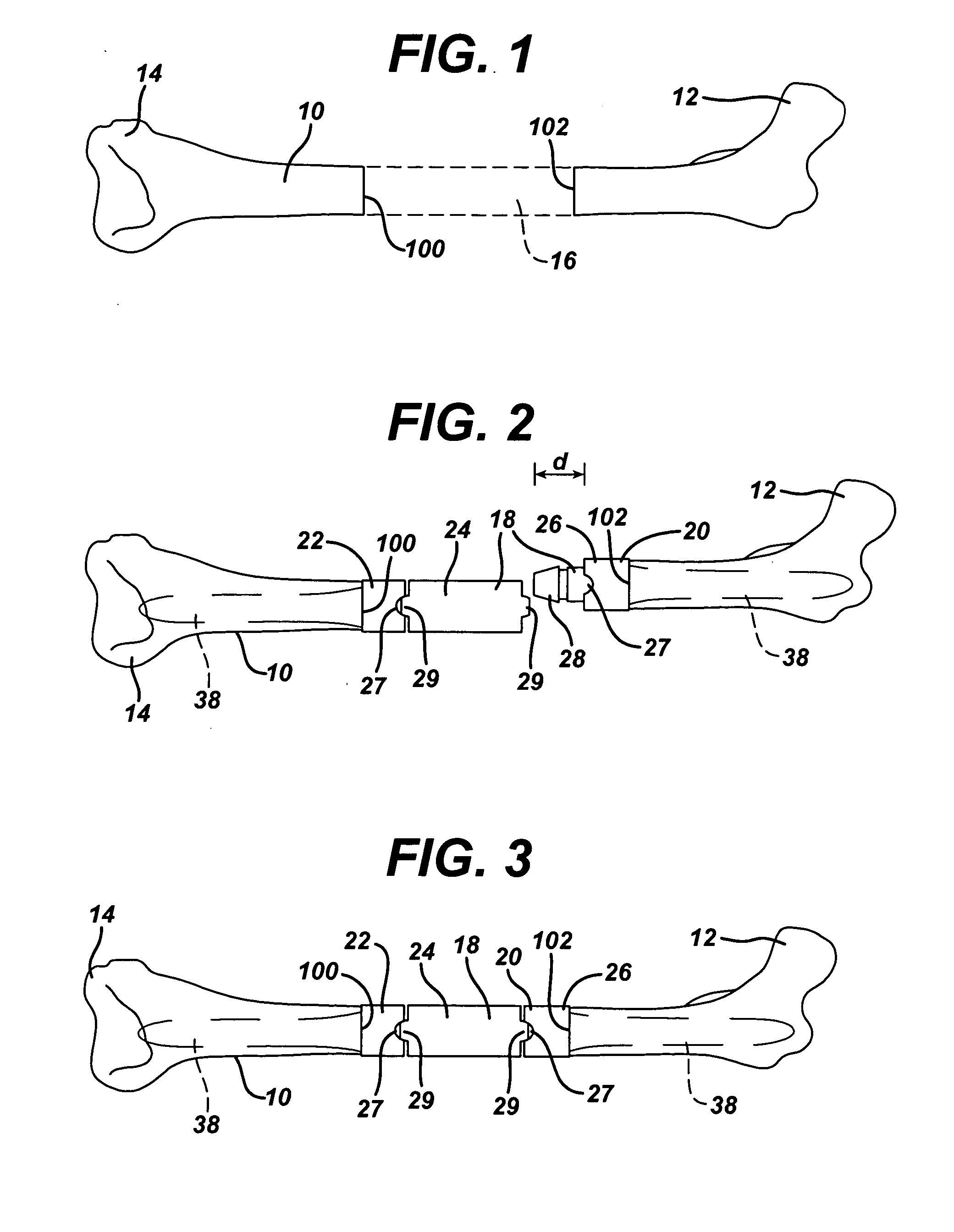
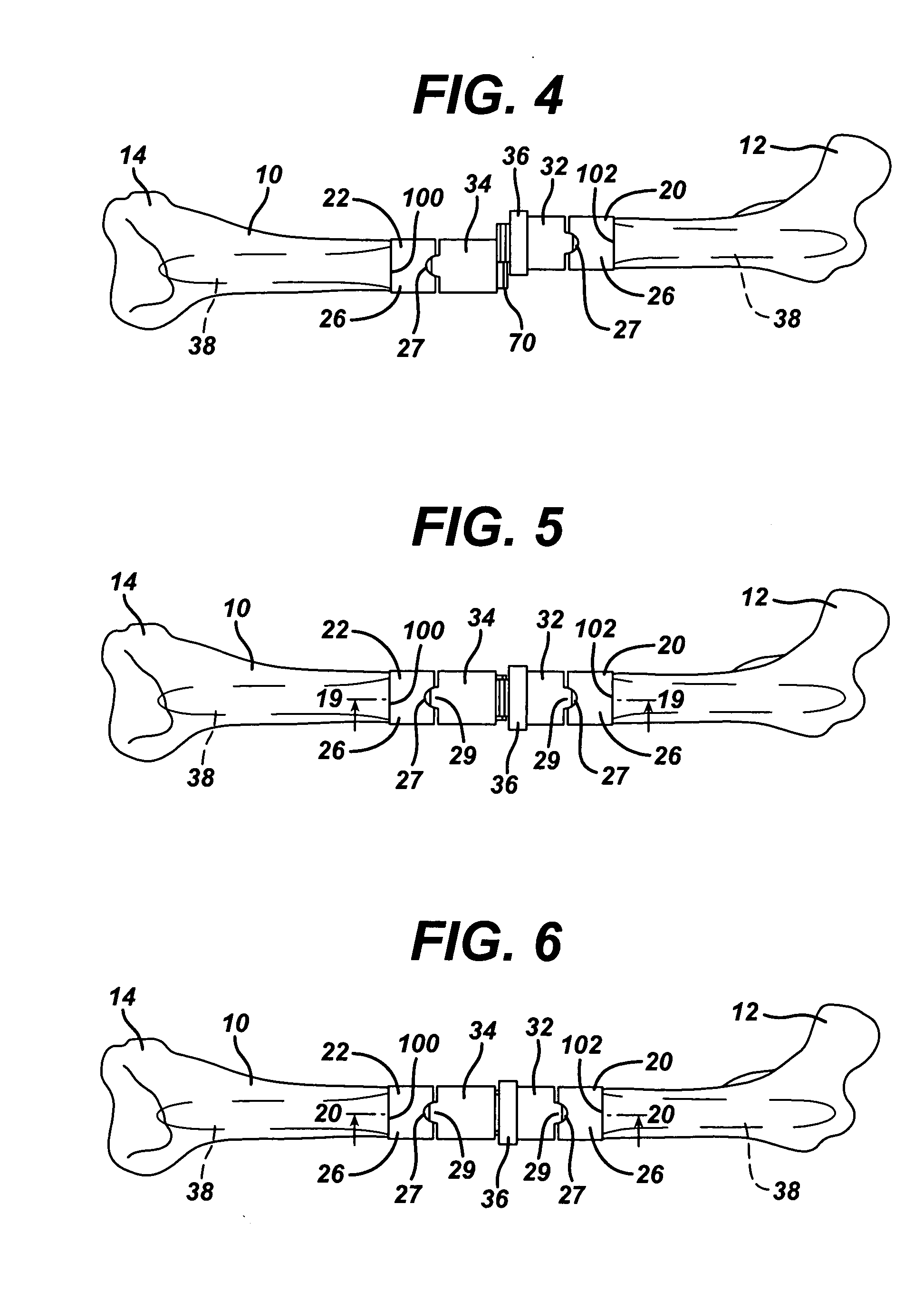
[0037]FIG. 1 illustrates a long bone, and in particular, a femur 10 with proximal and distal ends 12, 14. The proximal end 12 of the femur 10 comprises the femoral head and adjacent bone tissue; the distal end 14 of the femur comprises the femoral condyles and adjacent bone tissue. FIG. 1 also illustrates in phantom the intercalary segment 16 of diaphyseal bone that has been removed, due to, for example, disease or severe trauma. Although the present invention is illustrated in use with the femur, it should be understood that the invention is not so limited; the invention could be used in any other long bone, such as the tibia or humerus, where a portion of the shaft has been removed or is missing.

[0038]FIG. 2 illustrates the femur 10 of FIG. 1 in an intra-operative state, with a modular mid-shaft prosthetic trial system 18, prior to connection of the trial components. FIG. 3 illustrates the femur and trial system 18 of FIGS. 1-2 after the trial components have been connected. The ...


PUM


Abstract

Two spacer components and a retaining ring are part of an orthopaedic system. The system may also include trial or implant stem components that are inserted or implanted in the proximal and distal ends of the long bone. One spacer segment has a male portion and the other spacer segment has a transverse female slot. The male portion and female slot are positioned to allow the male portion to be moved into and out of the female slot in a direction other than the proximal-distal direction. The retaining ring is then threaded into a locked position to limit relative movement between the male portion and female slot. The spacer segments can thus be connected after the segments have been connected to the native bone without damaging the soft tissue at the native bone through distraction.

Description

CROSS-REFERENCE TO RELATED APPLICATIONS [0001] The present application is a continuation-in-part of U.S. patent application Ser. No. 10 / 403,612, entitled “Dovetailed Intercalary Segmental Implant” filed on Mar. 31, 2003, by Stephen A. Hazebrouck, which is incorporated by reference herein in its entirety.FIELD OF THE INVENTION [0002] The present invention relates to prosthetic systems for replacement of parts of bones, and more particularly to prosthetic systems having components that can be connected and disconnected in situ without damaging soft tissue through distraction of bone segments. BACKGROUND OF THE INVENTION [0003] Severe trauma and disease can lead to significant amounts of bone loss. In some instances, it is necessary to excise intercalary bone from a long bone, that is, part of the diaphysis or bone shaft between the ends of the long bone, but it is not necessary to excise the ends of the long bone. Thus, for example, a portion of the shaft of the femur may need to be e...

Claims


Application Information

Patent Timeline
Patent Type & Authority Applications(United States)
IPC IPC(8): A61F2/00A61F2/28A61F2/30A61F2/36A61F2/38A61F2/46
CPCA61F2/28A61F2310/00029A61F2/36A61F2/3859A61F2/389A61F2/4684A61F2002/2825A61F2002/2853A61F2002/2892A61F2002/30143A61F2002/30224A61F2002/30329A61F2002/30332A61F2002/30382A61F2002/30383A61F2002/30385A61F2002/30387A61F2002/30405A61F2002/30492A61F2002/30507A61F2002/30599A61F2002/30604A61F2002/30616A61F2002/30772A61F2002/30774A61F2002/30789A61F2002/30795A61F2002/3082A61F2002/30878A61F2002/4638A61F2002/4642A61F2220/0025A61F2220/0033A61F2230/0017A61F2230/0069A61F2250/0063A61F2310/00023A61F2/30721A61F2002/30331A61F2/4637
Inventor HAZEBROUCK, STEPHEN ANDRE'
Owner DEPUY PROD INC
Learn More