
X-ray apparatus with a component controllable from the x-ray detector

a technology of x-ray detector and component, applied in the field of x-ray apparatus, can solve the problems of high space requirement, high cost and time-consuming of producing the known control devi

Inactive Publication Date: 2005-05-19
SIEMENS AG
View PDF8 Cites 15 Cited by
  • Summary
  • Abstract
  • Description
  • Claims
  • Application Information

AI Technical Summary

Benefits of technology

[0013] According to a further embodiment, a power source, preferably an accumulator, is contained in the housing. This measure likewise contributes to a wireless execution of the x-ray detector. Furthermore, an interface for hardwired transmission of data can be provided on the housing. This can be a conventional interface, for example a USB interface or the like. By means of such an interface, for example, updated versions of computer programs can be transmitted to the electronics in a simple manner.
[0014] The detector plate can be formed of a number of detector elements arranged in the X— and Y-directions (columns and rows). The detector elements form a detector matrix. The detector elements can be produced from amorphous silicon, and can be accommodated on a glass or plastic substrate. The detector elements, for example, can be photodiodes or elements for charge measurement (CCD elements). The execution of the detector elements from amorphous silicon enables miniaturized manufacturing in a relatively simple manner. In addition, the matrix can include CMOS chips that enable a further degree of integration. For example, intensifiers, ADCs (analog to digital converters) or other electronic circuits can be directly integrated in the large-area CMOS structure.

Problems solved by technology

The need for a specific control device for representation of an acquired x-ray image as well as to control the functions of the x-ray apparatus results in a relatively high space requirement.
Aside from this, the production of the known control device is expensive and time-consuming.

Method used


Image

  • X-ray apparatus with a component controllable from the x-ray detector
  • X-ray apparatus with a component controllable from the x-ray detector
  • X-ray apparatus with a component controllable from the x-ray detector

Examples


first embodiment

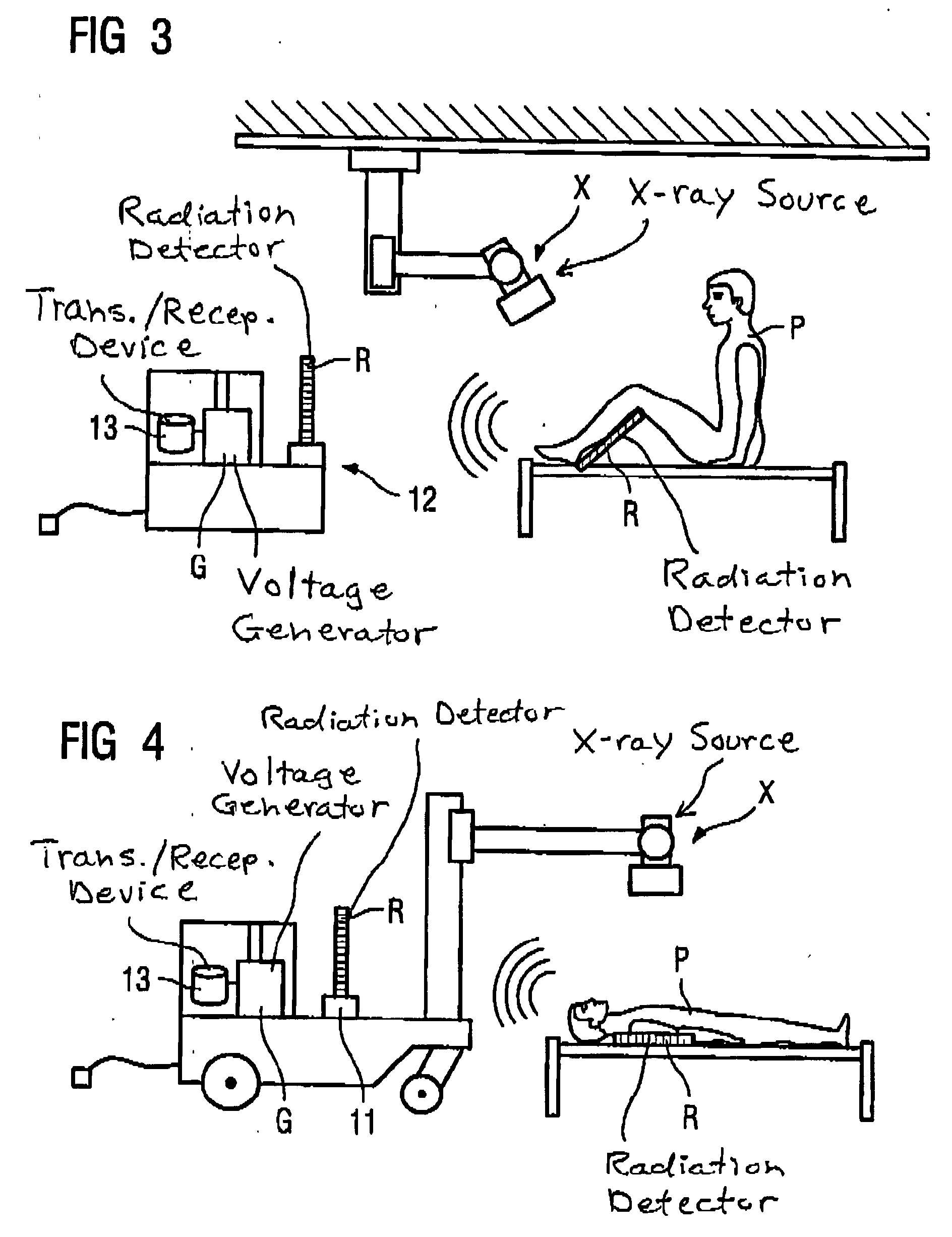
[0023]FIG. 3 shows an inventive x-ray apparatus. The x-ray detector shown in FIG. 2 is designated with the reference character R and an x-ray radiator is designated with the reference character X. A generator G for generation of the high voltage necessary for operating the x-ray radiator X can be provided with a charging station 12 for acceptance of the x-ray detector R. Upon placement or connection of the x-ray detector with the charging station 12, connection of a data line (not shown) provided on the charging station 12 with the aforementioned interface can also be established; an automatic readout of image data stored in the electronics 8 can ensue. The unit housing the generator G can also has a further transmission / reception device 13 to receive and send data.

second embodiment

[0024]FIG. 4 shows an inventive x-ray apparatus. The x-ray radiator X, the generator G, the charging station 12 and the further transmission and reception device are thereby combined into a mobile unit.

[0025] The function of the x-ray detector as well as of the x-ray apparatus is as follows:

[0026] X-ray radiation emitted by the x-ray radiator X penetrates a subject, for example a patient P shown in FIGS. 3 and 4. The absorption pattern of the x-ray radiation is imaged on the detector plate 1. The values measured by the detector elements 3 are read out, digitized, intensified and transduced into image information line-by-line for each of the detector elements 3 by of the electronics 8. A digital image produced by of the electronics 9 can immediately be shown on the flat screen 10.

[0027] The flat screen 10 is fashioned as a “touch panel”, meaning specific functions can be triggered by contact of function areas displayed on the screen. Thus, for example, the x-ray image displayed on ...


PUM

PropertyMeasurementUnit
poweraaaaaaaaaa
voltageaaaaaaaaaa
areaaaaaaaaaaa

Abstract

An x-ray apparatus has an x-ray source and a radiation detector, the radiation detector having a housing with a detector plate disposed at front side thereof, electronics contained in the housing for processing electrical signals generated by the detector plate dependent on incident radiation to produce image signals, and a flat screen, supplied with said image signals, disposed at a rear side of the housing for displaying the x-ray image. The flat screen includes a touch panel, and the x-ray apparatus further includes a controllable component, in communication with the radiation detector, controllable by entries made via the touch panel of the radiation detector.

Description

BACKGROUND OF THE INVENTION [0001] 1. Field of the Invention [0002] The present invention concerns an x-ray apparatus of the type having a radiation detector having a flat screen display at which an x-ray image, acquired by a detector plate of the radiation detector, can be presented. [0003] 2. Description of the Prior Art [0004] An x-ray detector is known from U.S. patent application Publication No. 2002 / 0150214. In this known x-ray detector, the acquired image data are transmitted to a control device via a wireless communication connection. An acquired image can be judged as its quality by a radiator by means of a monitor provided at the control device. Acquired x-ray images can also be transmitted to an x-ray image archiving system. The need for a specific control device for representation of an acquired x-ray image as well as to control the functions of the x-ray apparatus results in a relatively high space requirement. Aside from this, the production of the known control device...

Claims


Application Information

Patent Timeline
Patent Type & Authority Applications(United States)
IPC IPC(8): G01T1/20A61B6/00G01N23/04G01T1/24G01T1/29G03B42/02
CPCA61B6/00A61B6/4233A61B6/462A61B6/467A61B6/4464G01N23/04G01T1/2018G01T1/2928A61B6/548A61B6/563G01T1/20188
Inventor SPAHN, MARTIN
Owner SIEMENS AG
Learn More