Methods and devices to control polymerization
a polymerization and polymerization technology, applied in the field of controlled curing of optical devices, can solve the problems of non-uniform distribution of light intensity over the lens-forming material, non-critical surface of the mold may refract radiation, scattering of light rays,
- Summary
- Abstract
- Description
- Claims
- Application Information
AI Technical Summary
Benefits of technology
Problems solved by technology
Method used
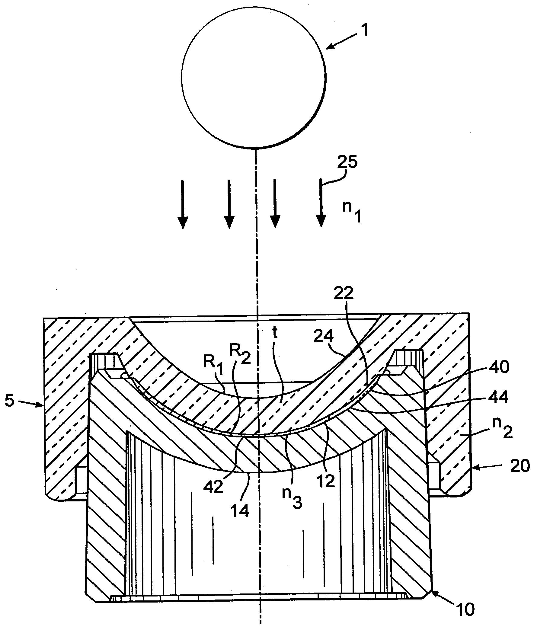
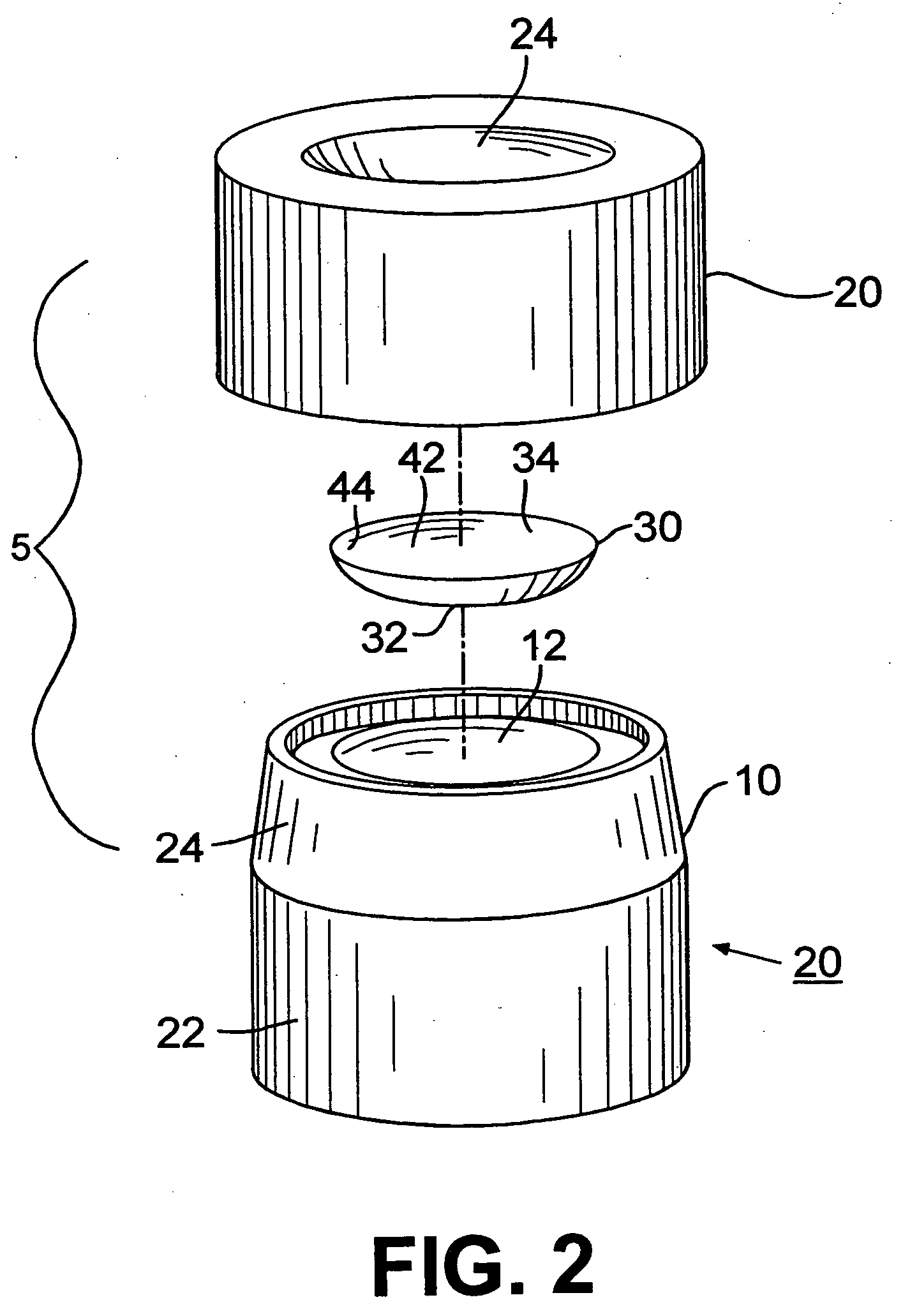
Image

Examples
example 1
[0061] A series of HEMA lenses was cast molded using posterior and anterior molds made from a non-UV stabilized PVC resin. The posterior mold concave surface of lot 2 was filled with glycerol; the posterior mold concave surface of lot 3 was filled with water. After casting, the mold assemblies were separated and lenses were hydrated and measured. Each lot had five lenses.
TABLE 1Lot #SAG (mm)1 (control)3.01823.59633.600
[0062] Lenses made with water or glycerol in the posterior cavity showed an increased SAG measurement when compared to the control lenses. The lots with increased SAG measurements showed a decrease in the number of lenses exhibiting dimpling.
example 2
[0063] A series of HEMA lenses was cast molded using posterior and anterior molds made from a non-UV stabilized PVC resin. The mold assemblies were separated and lenses were hydrated and measured. Lot 1 had 89 lenses, Lot 2 had 69 and Lot 3 had 27. Lot 3 had a controlled non-critical surface (no junctions present). A 58.8 D magnifier lens was used as the optical lens.
TABLE 2Non-CriticalClampSurfacePlatePower ofAverageLot No.Posterior MoldTreatmentContact LensSAG1 (control)StandardNo−63.298Surface, Bevelcondensinglens2Optical Quality58.8 D−63.372Surface, Bevelcondensinglens3Controlled58.8 D−63.451curvecondensinglens
[0064] The lenses cured with a magnifying lens showed an increase in SAG measurements as compared to the control lenses (lot 1).
example 3
[0065] A series of HEMA lenses was cast molded using posterior and anterior molds made from a non-UV stabilized PVC resin. The mold assemblies were separated and lenses were hydrated and measured. Each lot had 5 lenses. Lot 1 was a control lot. An asymmetric convex plug having a power of 117 D made of Topas was inserted into the posterior concave surface of lot 2. The surface of the plug toward the optical source had a radius of 7.00 mm and the surface of the plug facing the non-critical surface of the mold had a radius of 8.5 mm. The SAG of the plug was 4.68 nm.
TABLE 3Lot No.SAG (average)1 (control)3.53423.658
[0066] The lenses made using an asymmetric convex plug made of Topas inserted showed an increase in SAG measurement and a lower incidence of dimpling. Overall, improved lenses were produced using the Topas insert.
PUM
| Property | Measurement | Unit |
|---|---|---|
| Radius | aaaaa | aaaaa |
Abstract
Description
Claims
Application Information
 - R&D
- Intellectual Property
- Life Sciences
- Materials
- Tech Scout
- Unparalleled Data Quality
- Higher Quality Content
- 60% Fewer Hallucinations
Browse by: Latest US Patents, China's latest patents, Technical Efficacy Thesaurus, Application Domain, Technology Topic, Popular Technical Reports.
© 2025 PatSnap. All rights reserved.Legal|Privacy policy|Modern Slavery Act Transparency Statement|Sitemap|About US| Contact US: help@patsnap.com