Microcomputer, electronic equipment, and debugging system

a microcomputer and electronic equipment technology, applied in the field of microcomputers and also electronic equipment and debugging systems, can solve the problems of not being able to acquire trace information for the portions necessary for debugging, being difficult to implement a trace range specification with external circuitry, and becoming difficult to obtain real-time trace information

Inactive Publication Date: 2005-05-12
SEIKO EPSON CORP
View PDF7 Cites 16 Cited by
  • Summary
  • Abstract
  • Description
  • Claims
  • Application Information

AI Technical Summary

Benefits of technology

[0010] In this aspect of the invention, it is possible to acquire information indicating that a plurality of instructions have been executed, using a single terminal. It is therefore possible to detect the occurrence of the execution of a plurality of instructions without substantially reducing the number of terminals that can be utilized by the user, which enables an increase in debugging efficiency.
[0038] This aspect of the invention makes it possible to provide a debugging system that can identify which instructions of debugging have been executed, even if a plurality of instructions are executed in a sequence that differs from the expected sequence, using a single terminal.

Problems solved by technology

However, if the internal operating frequency of the microcomputer 302 of the CPU-switching ICE rises, it becomes difficult to obtain a real-time trace, due to delays in the signals generated by the probe 306 and the buffer that stores trace information.
In addition, if an attempt is made to store trace information in a trace buffer without limitations, the trace buffer would soon overflow so that it may not be possible to acquire trace information for the portions necessary for debugging.
However, if the internal operating frequency of the CPU were to rise, it would become difficult to implement a trace range specification with external circuitry such as that of a CPU-switching ICE.
These terminals are necessary only during debugging, however, so they are useless as far as the end user is concerned and thus it is preferable to reduce them as far as possible.

Method used


Image

  • Microcomputer, electronic equipment, and debugging system
  • Microcomputer, electronic equipment, and debugging system
  • Microcomputer, electronic equipment, and debugging system

Examples


Embodiment Construction

[0052] Preferred embodiments of the present invention are described below with reference to the accompanying drawings.

1. Characteristics of the Present Embodiment

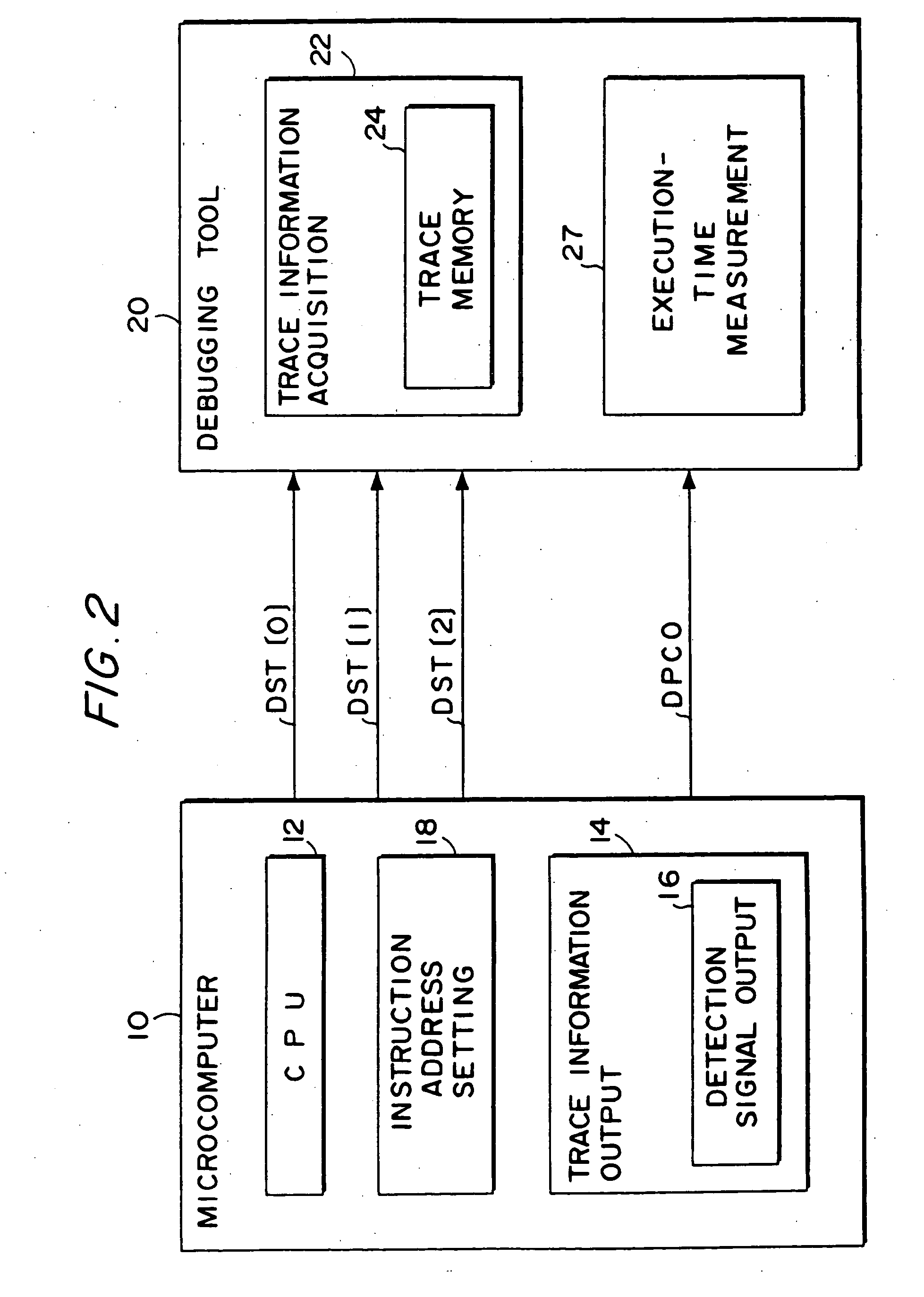
[0053] The description first concerns the configuration of an embodiment of the present invention, referring to FIG. 2.

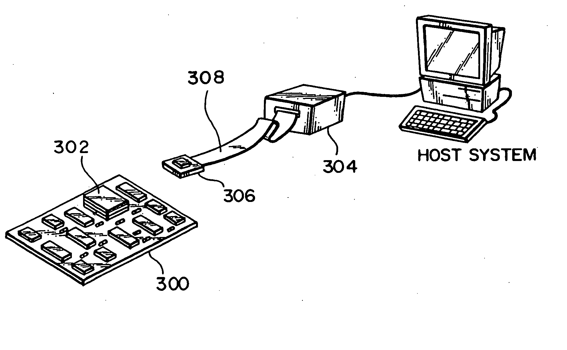
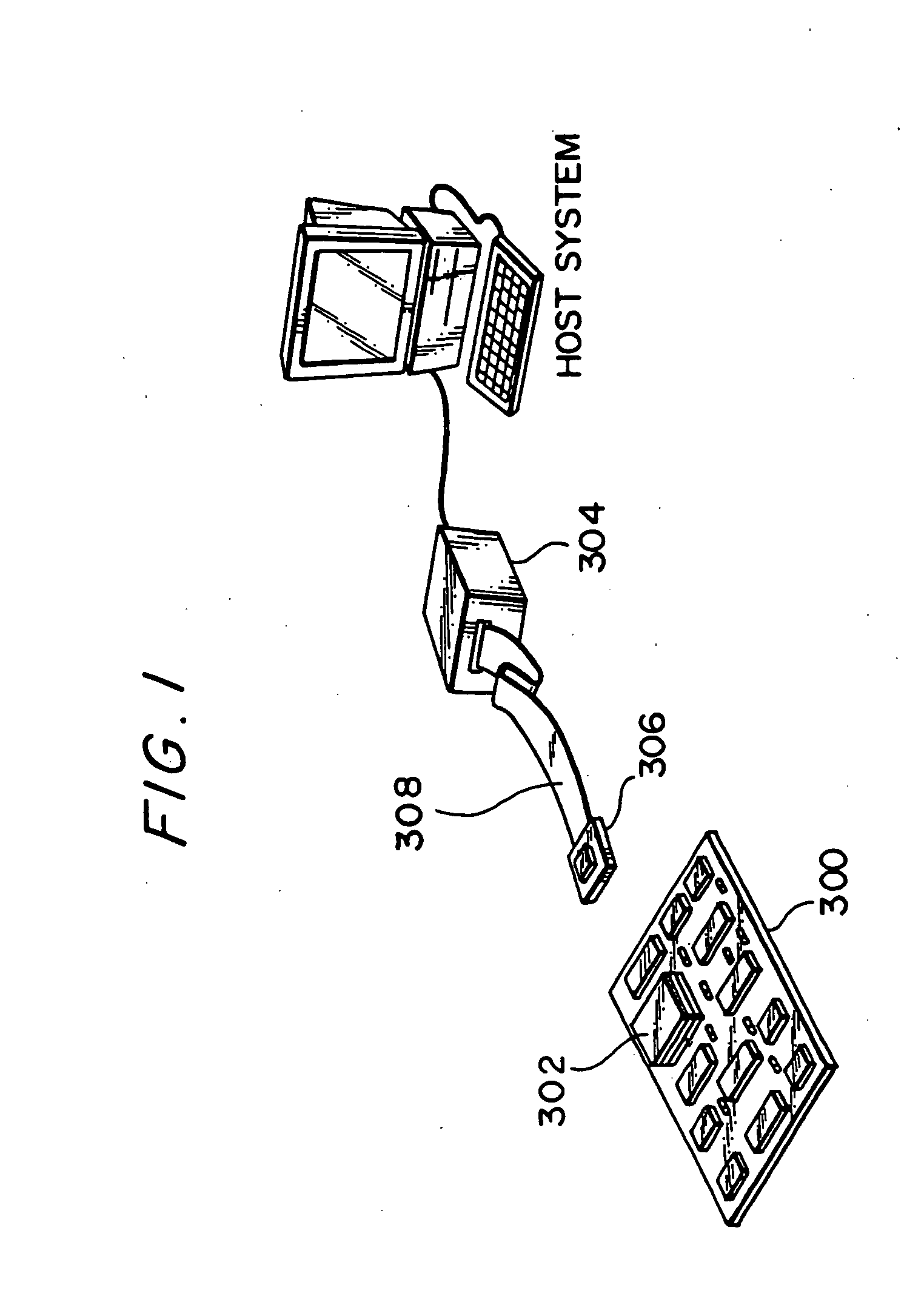
[0054] As shown in FIG. 2, a microcomputer 10 of this embodiment comprises a central processing unit (CPU) 12, an instruction address setting section 18, and a trace information output section 14. The trace information output section 14 comprises a detection signal output section 16.

[0055] An external debugging tool 20 of this microcomputer 10 comprises a trace information acquisition section 22 and a execution-time measurement section 27.

[0056] In this case, the trace information output section 16 outputs trace information for implementing a real-time trace, to four dedicated terminals. More specifically, it outputs instruction execution status information (DST[2:0]) of the CPU to three terminals at ...


PUM


Abstract

The present invention provides a microcomputer that makes it possible to implement a real-time trace on a mass-produced chip using few terminals, acquire trace information from within a specified range, and measure execution times, together with electronic equipment and a debugging system comprising this microcomputer. A trace information output section (16) outputs trace information for implementing a real-time trace, to four dedicated terminals. It outputs instruction execution status information (DST[2:0]) of the CPU to three terminals and the PC value (DPCO) of a branch destination when an PC absolute branch has occurred, serially to one terminal. A microcomputer (10) outputs information indicating the start and end of a trace range or execution-time measurement range to DST[2] in a predetermined sequence. A debugging tool (20) determines the start and end of the trace range or execution-time measurement range from the values in DST[2].

Description

TECHNICAL FIELD [0001] The present invention relates to a microcomputer and also to electronic equipment and a debugging system comprising the same. BACKGROUND OF ART [0002] There has recently been increasing demand for the incorporation of microcomputers that are capable of implementing high-level information processing into electronic equipment such as game machines, car navigation systems, printers, and portable information terminals. Such a thus-incorporated microcomputer is usually mounted on a user board called a target system. A software development support tool called an in-circuit emulator (ICE) is widely used for supporting the development of software to be used in the target system. [0003] The CPU-switching type of ICE shown in FIG. 1 is the most common type of this kind of ICE used in the art. With this CPU-switching ICE, a microcomputer 302 is removed from a target system 300 during debugging, and a probe 306 of a debugging tool 304 is connected thereto instead. This de...

Claims


Application Information

Patent Timeline
Patent Type & Authority Applications(United States)
IPC IPC(8): G06F11/28G06F11/22G06F11/36G06F15/78
CPCG06F11/3636G06F2201/88G06F11/3656G06F11/3648
Inventor MIYAYAMA, YOSHIYUKIKUDO, MAKOTOHIJIKATA, YOICHI
Owner SEIKO EPSON CORP
Why Eureka
Try Eureka