
Microwave energized plasma lamp with dielectric waveguide

a dielectric waveguide, plasma lamp technology, applied in waveguides, structural circuit elements, sustainable buildings, etc., can solve the problem of longer useful lifetimes than other lamps, and achieve the effect of minimizing power reflected and minimizing power reflected

Inactive Publication Date: 2005-05-12
LUXIM CORP
View PDF98 Cites 52 Cited by
  • Summary
  • Abstract
  • Description
  • Claims
  • Application Information

AI Technical Summary

Benefits of technology

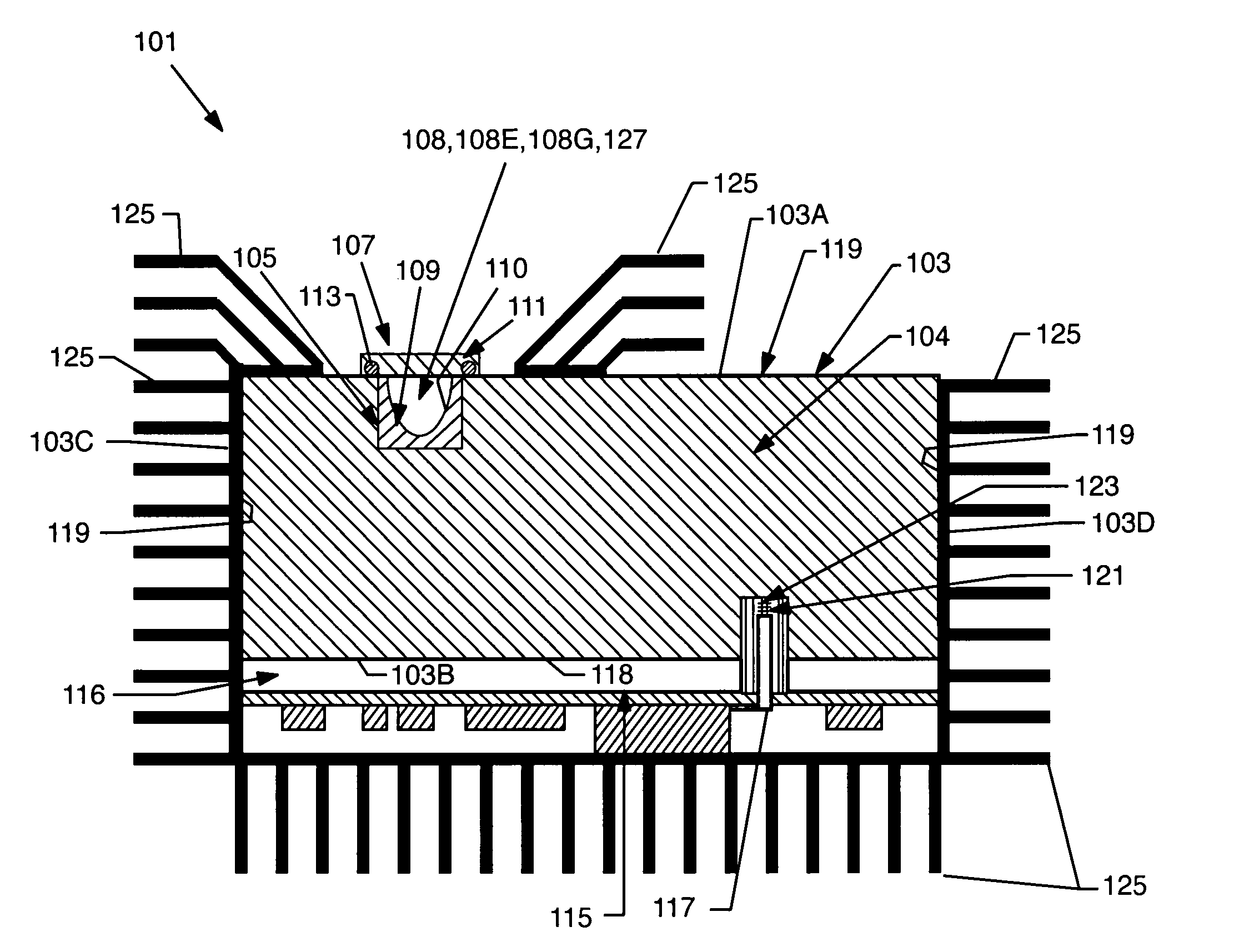
[0007] In a second aspect the invention provides a lamp including a waveguide having a body including at least one dielectric material with a dielectric constant greater than approximately 2. A first microwave probe positioned within the body is connected to an output of a source of microwave power operable at at least one frequency such that the body resonates in at least one resonant mode having at least one electric field maximum. A second microwave probe, positioned within the body, is connected to a source input. At least one lamp chamber, integrated with the body, contains a fill mixture which when receiving power provided by the resonating body forms a light-emitting plasma. The lamp further includes means for minimizing power reflected from the body back to the source.
[0008] In a third aspect the invention provides a lamp including a waveguide having a body including at least one dielectric material with a dielectric constant greater than approximately 2. A first microwave probe positioned within the body is connected to an output of a source of microwave power operable at at least one frequency such that the body resonates in at least one resonant mode having at least one electric field maximum. A second microwave probe, positioned within the body, is connected to a source input. A third microwave probe is connected to the source output. At least one lamp chamber, integrated with the body, contains a fill mixture which when receiving power provided by the resonating body forms a light-emitting plasma. The lamp further includes means for minimizing power reflected from the body back to the source.

Problems solved by technology

Because electrodes are not used, they often have longer useful lifetimes than other lamps.

Method used


Image

  • Microwave energized plasma lamp with dielectric waveguide
  • Microwave energized plasma lamp with dielectric waveguide
  • Microwave energized plasma lamp with dielectric waveguide

Examples


Embodiment Construction

[0042] While the present invention is open to various modifications and alternative constructions, the preferred embodiments shown in the drawings will be described herein in detail. It is to be understood, however, there is no intention to limit the invention to the particular forms disclosed. On the contrary, it is intended that the invention cover all modifications, equivalences and alternative constructions falling within the spirit and scope of the invention as expressed in the appended claims.

[0043] As used herein, the terms “dielectric waveguide integrated plasma lamp”, “DWIPL”, “microwave energized plasma lamp with solid dielectric waveguide”, and “lamp” are synonymous, and the term “lamp body” is synonymous with “waveguide body”. The term “probe” herein is synonymous with “feed” in the '718 application. The term “power”, i.e., energy per unit time, is used herein rather than “energy” as in the '718 application. The terms “lamp chamber” and “hole” herein are synonymous with...


PUM


Abstract

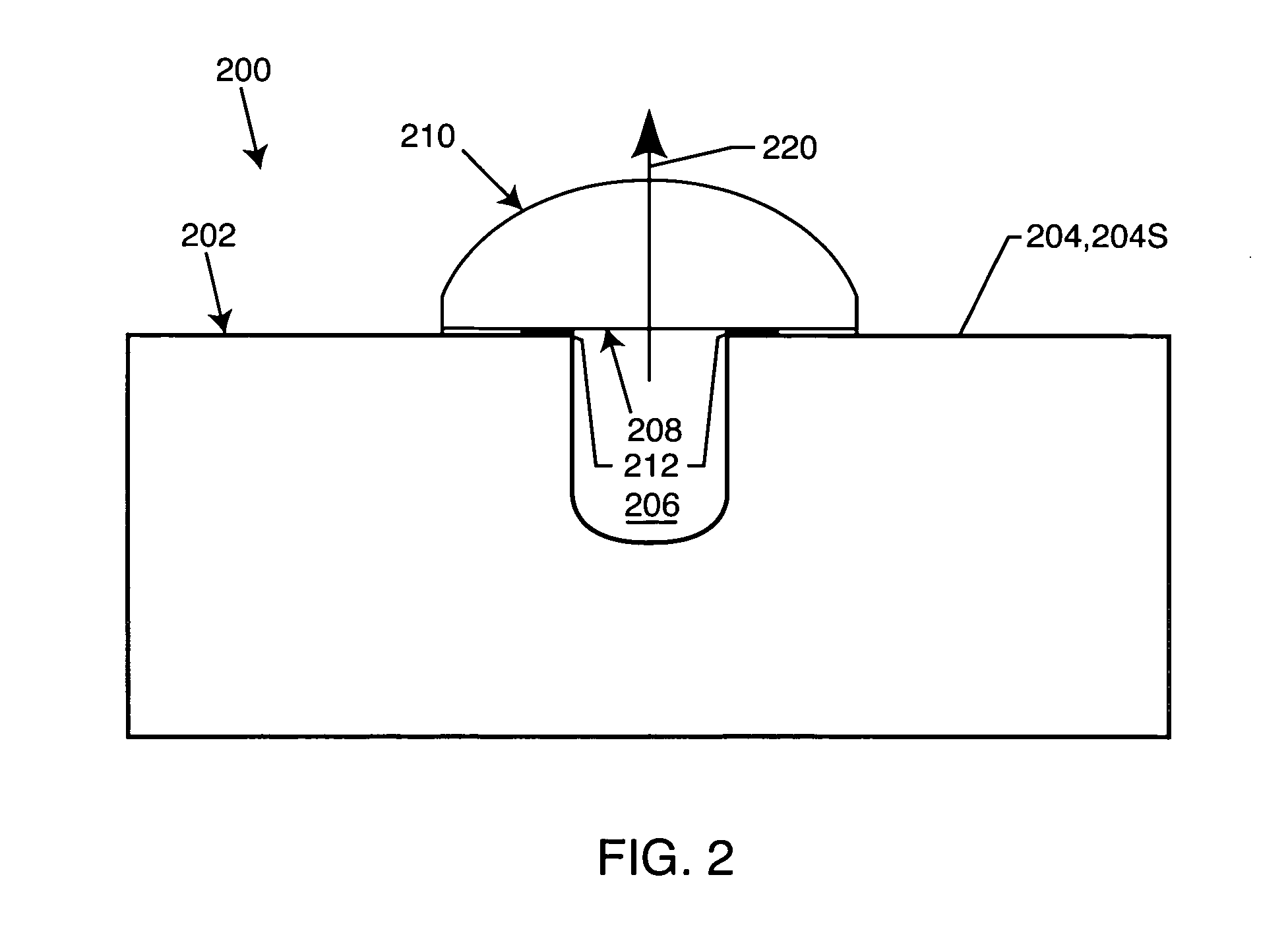
A plasma lamp including a waveguide body consisting essentially of at least one solid dielectric material. The body is coupled to a microwave power source which causes the body to resonate in at least one resonant mode. A lamp chamber integrated into the body contains a fill mixture which forms a light-emitting plasma when the chamber receives microwave power from the resonating waveguide body. The chamber has an aperture sealed to the external environment by a window or lens allowing light to be transmitted. Alternatively, the fill is in a self-enclosed bulb positioned in the chamber. Embodiments disclosed include lamps having a drive probe and a feedback probe, and lamps having a drive probe, feedback probe and start probe, which minimize power reflected from the body back to the source both before the plasma is formed and after it reaches steady state.

Description

CROSS-REFERENCE TO RELATED APPLICATIONS [0001] This application is a continuation of application Ser. No. 10 / 356,340 filed on Jan. 31, 2003 and entitled “Microwave Energized Plasma Lamp With Dielectric Waveguide,” which is a continuation-in-part of application Ser. No. 09 / 809,718 (“'718”), filed on Mar. 15, 2001 and issued as U.S. Pat. No. 6,737,809 B2 and entitled “Plasma Lamp With Dielectric Waveguide”, which claimed benefit of priority of provisional patent application Ser. No. 60 / 222,028, filed on Jul. 31, 2000 and entitled “Plasma Lamp”. Application Ser. Nos. 09 / 809,718 and 60 / 222,028 are incorporated herein in their entirety by this reference.BACKGROUND OF THE INVENTION [0002] 1. Field of the Invention [0003] This invention relates to devices and methods for generating light, and more particularly to electrodeless plasma lamps energized by microwave radiation. Rather than using a waveguide with an air-filled resonant cavity, embodiments of the invention use a waveguide having ...

Claims


Application Information

Patent Timeline
IPC IPC(8): H01JH01J1/00H05B41/24H01J7/46H01J61/02H01J61/12H01J61/30H01J61/52H01J61/56H01J65/04H01P3/16H05B37/00H05B41/16H05B41/26
CPCH01J61/025H01J61/12H01J61/30Y02B20/22H01J65/044H01P3/16H01J61/52Y02B20/00H01J7/46H01J65/04
Inventor ESPIAU, FREDERICK M.CHANG, YIAN
Owner LUXIM CORP
Learn More