
High pressure discharge lamp

a discharge lamp and high-pressure technology, applied in the direction of discharge tube/lamp details, discharge tube luminescnet screens, gas-filled discharge tubes, etc., can solve the problems of insufficient operating service life, inability to achieve long enough operating service life, and inability to efficiently produce thorium dioxide. , to achieve the effect of long operating service life and high degree of reduction of thorium dioxid

Active Publication Date: 2005-05-12
USHIO DENKI KK
View PDF4 Cites 10 Cited by
  • Summary
  • Abstract
  • Description
  • Claims
  • Application Information

AI Technical Summary

Benefits of technology

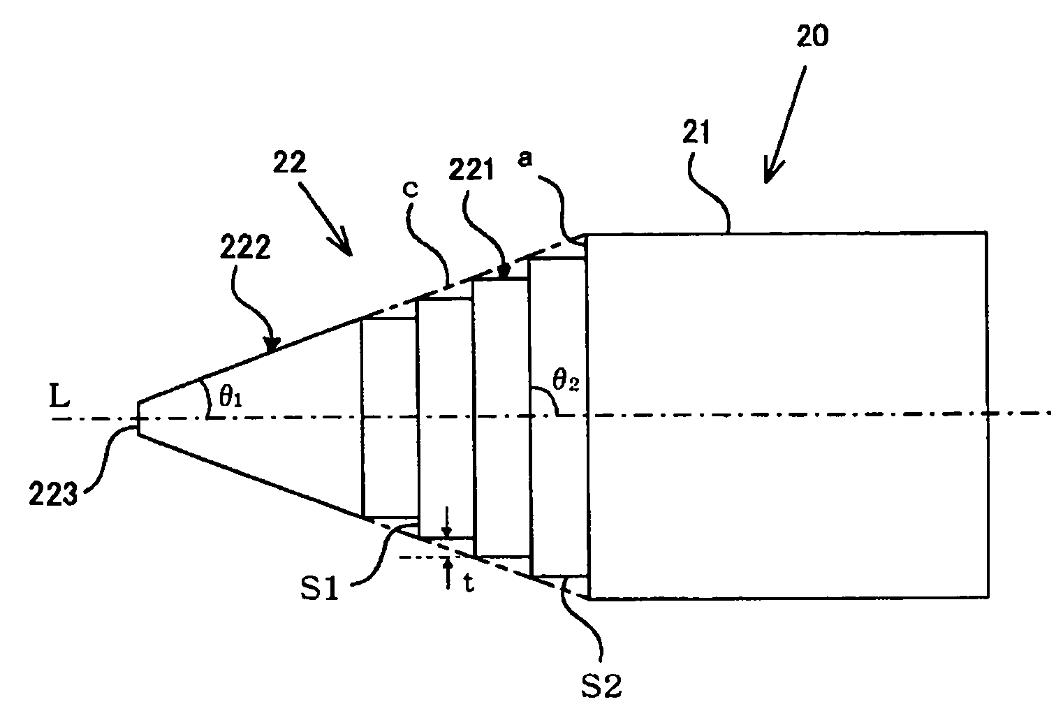
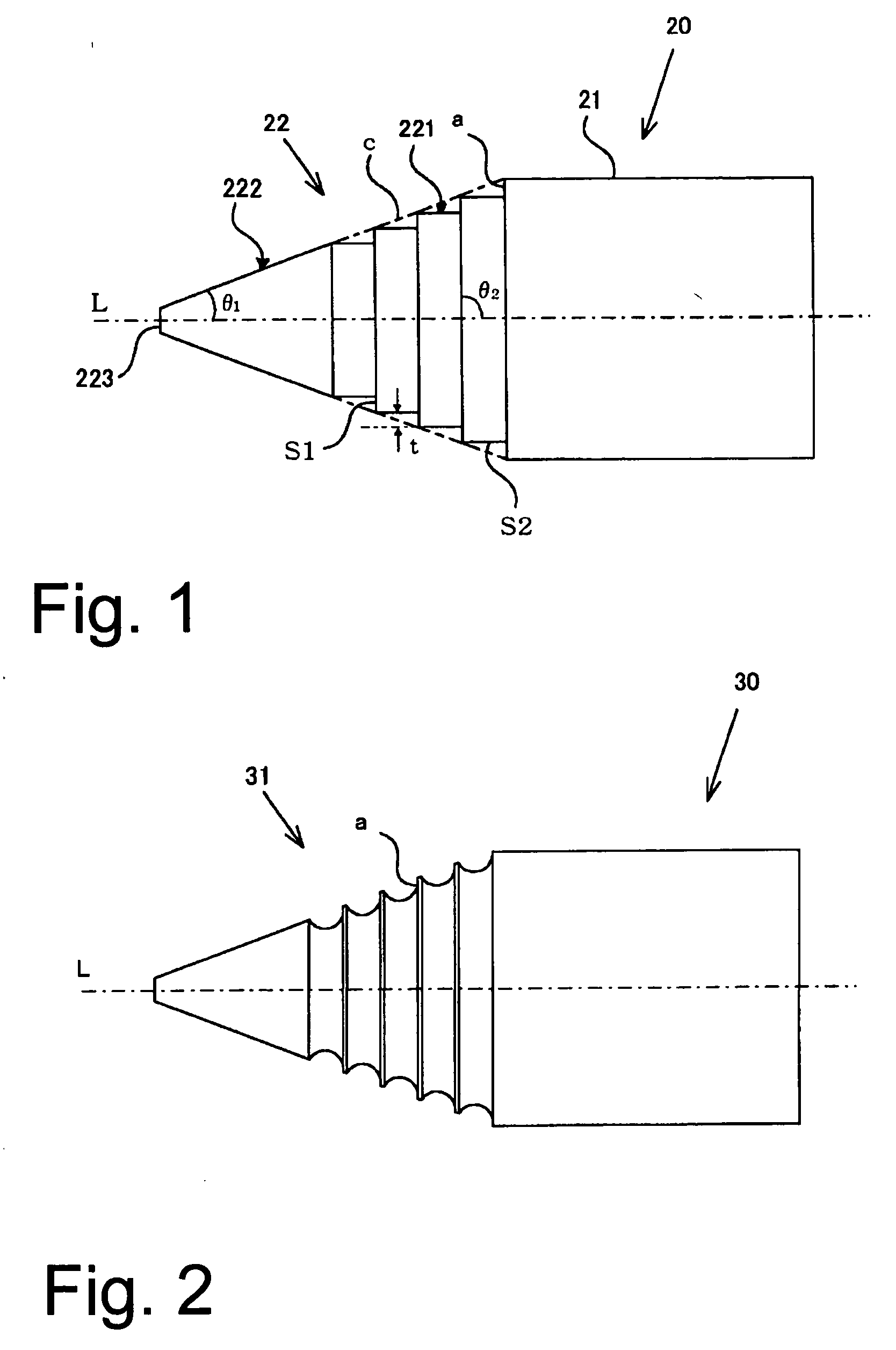
[0018] By the high pressure discharge lamp of the invention, by the measure that the base part of the cone in the conical area of the cathode rises with an angle θ2 greater than the angle of inclination θ1 with respect to this base part and is opposite the discharge arc and that the base part of the cone has light receiving surface areas which receive the radiant light from this discharge lamp arc, these light receiving surface areas absorb the radiant heat from the discharge arc. As a result, the temperature of this base part of the cone becomes high; this leads to reliable implementation of a high degree of reduction of the thorium dioxide in the entire cone part. Therefore, it becomes possible to use the expected amount of thorium for stable formation of the discharge arc. As a result, in a high pressure discharge lamp the expected long operating service life can be reliably obtained.

Problems solved by technology

Therefore, thorium which acts as an emitter cannot be efficiently produced.
Therefore, thorium dioxide cannot be used with high efficiency.
As a result of the fact that the absolute amount of thorium which in fact contributes to the formation of the discharge arc decreases, therefore, there is the disadvantage that in the high pressure discharge lamp 10 a long enough operating service life cannot be obtained.
Therefore, a high enough degree of reduction of the thorium dioxide cannot be implemented.
Thus, it was found that there is the disadvantage that in this high pressure discharge lamp 10 the expected service life cannot be achieved.

Method used


Image

  • High pressure discharge lamp
  • High pressure discharge lamp
  • High pressure discharge lamp

Examples


embodiment

[0040] Embodiment

[0041] (Comparison Example)

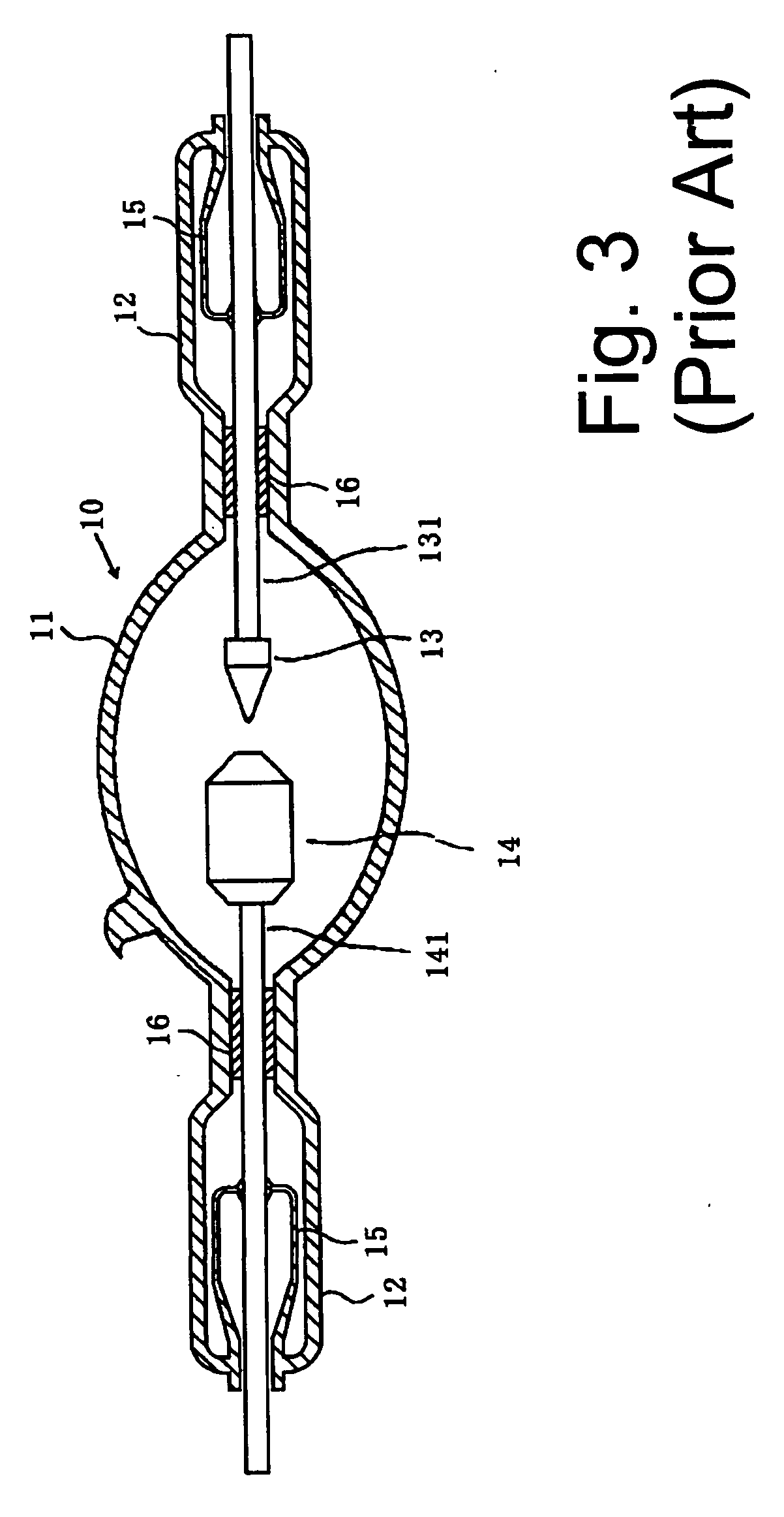
[0042] A xenon lamp with the arrangement shown in FIG. 3 is produced, with an output power of 2 kW and an operating pressure of 8 MPa, in which the interior of a silica glass bulb is filled with xenon gas. This xenon lamp has a cathode with the arrangement shown in FIG. 4. The material thereof is tungsten which has been doped with a ratio of 2% by weight thorium dioxide. The diameter of the tip area of the cathode is 0.4 mm, the angle of inclination θ1 with respect to the tip area of the cone is 40° and the diameter of the body part is 6 mm. In the xenon lamp obtained the operating service life was measured. It was 1150 hours.

[0043] (Embodiment)

[0044] A xenon lamp was produced in the same way as the above described comparison example, except for the fact that a cathode with the arrangement shown in FIG. 1 was used. In this xenon lamp, the width t in the radial direction of the step surface S1 in the step region of the base part 221 of t...


PUM


Abstract

A high pressure discharge lamp in which the cathode has a cylindrical body part and a conical part which is doped with thorium dioxide (ThO2), and with a diameter which decreases in a direction from the body part toward the tip area of the conical part by at least one light receiving surface area being formed between the body part and the tip area of the cone in a base part of the conical part. The light receiving area lies at an angle with respect to the center axis of the conical part and the body part, said angle which is measured from the side of the body part being greater than the angle of inclination which is formed between the outer periphery of the conical part in the tip area of the cone and the center axis.

Description

BACKGROUND OF THE INVENTION [0001] 1. Field of the Invention [0002] The invention relates to a high pressure discharge lamp, such as a xenon lamp, a high pressure mercury lamp, or the like. The xenon lamp is used, for example, in a projection apparatus or the like using DLP (digital light processing) technology as a light source. The high pressure mercury lamp is used, for example, as a light source in a semiconductor exposure device of a liquid crystal exposure device, a device for exposure of a printed board or the like. [0003] 2. Description of Related Art [0004] Conventionally, a lamp with the arrangement which is shown by way of example in FIG. 3 is known as a high pressure discharge lamp. This high pressure discharge lamp 10 is made of a silica glass bulb which has a light emitting part 11 and hermetically sealing parts 12. Furthermore, the high pressure discharge lamp 10 consists of a cathode 13 and an anode 14 which are located within the light emitting part 11 opposite one ...

Claims


Application Information

Patent Timeline
Patent Type & Authority Applications(United States)
IPC IPC(8): H01J17/04H01J17/20H01J61/04H01J61/06H01J61/073
CPCH01J61/0735H01J61/0732
Inventor KIKUCHI, YASUROINAOKA, NORIHIROFUJINA, KYOSUKE
Owner USHIO DENKI KK
Learn More