
Method and apparatus for digital detection of electromagnetic signal strength and signal direction in metallic pipes and cables

a technology applied in the field of digital detection of electromagnetic signal strength and signal direction in metallic pipes and cables, can solve the problems of difficult reliable determination of signal direction, significant radio frequency interference on the signal received by the receiver, and difficult calibration process itself, so as to reduce the requirements of analog front-end hardware, reduce calibration and test time, and wide resistance to component tolerances

Active Publication Date: 2005-05-05
BUSAN TRANSPORTATION CORPORATION
View PDF29 Cites 55 Cited by
  • Summary
  • Abstract
  • Description
  • Claims
  • Application Information

AI Technical Summary

Benefits of technology

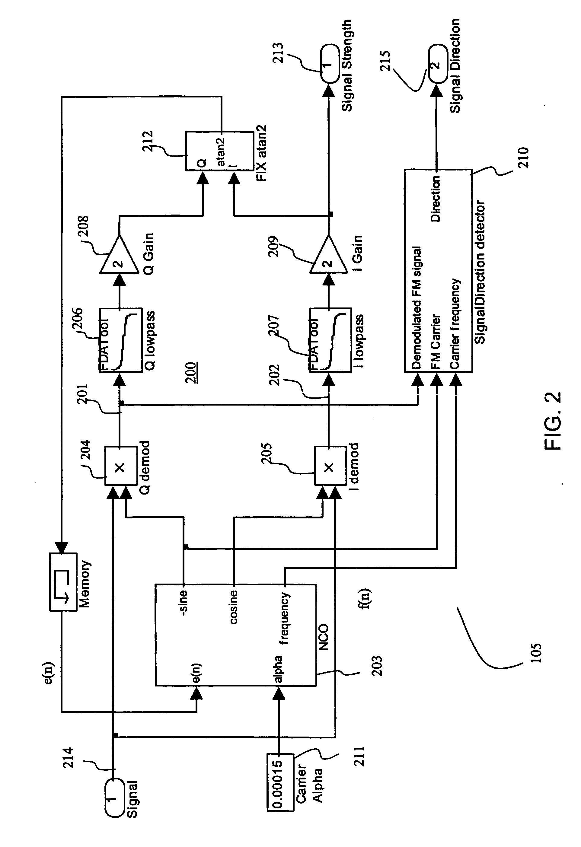
[0023] In accordance with the invention, a digital line locator receiver architecture with significantly reduced analog front-end hardware requirements, wide resistance to component tolerances, lower calibration and test time, and flexible frequency selectivity is presented. Line locators according to some embodiments of the present invention provide accurate estimation of the fundamental physical parameters of line location (electromagnetic signal strength and signal direction) in extremely noisy environments.
[0028] Line locators implemented according to embodiments of the present invention can provide a reliable signal direction measurement at all times when the field strength (which is related to the amplitude of the signal generated by a detector in response to the electromagnetic field) is displayed. This ability directly leads to increased confidence that the indications of line current, depth, centerline position, and field strength provided by the line location system refer to the primary tracked cable or pipe; rather than an adjacent line that is carrying an electromagnetically induced ground return current.

Problems solved by technology

Significant radio frequency interference on the signal received by the receiver can be present in the environment over this range.
The calibration process itself is often problematic due to interference and noise sources, including those present in the environment and the receiver itself.
Even with this potential benefit, signal direction is not commonly present on line locating systems because the reliable determination of the signal direction is difficult.
Unfortunately, there are several drawbacks to these approaches.
The first problem is that the user must pause periodically and reset the phase reference to a new position, before enough distance has been traversed that the phase reference changes sign on the primary targeted conductor.
A second problem has to do with variability in the physical transmission medium of the cable or pipe, particularly at higher locate frequencies which are more susceptible to capacitive coupling.
Unfortunately, one cannot know this characteristic a priori, so the phase of the signal can change in unknown ways as the receiver is moved along the line.
This compromises the ability to determine the phase reference point.
A third drawback to approaches that rely on the simultaneous transmission of disjoint frequencies is that the receiver hardware system becomes more complex in order to accurately process both component signals.
The elegance of this approach is offset by the difficulty of comparing signal phases as described in U.S. Pat. No. 6,411,073.
An error larger than this will result in a false detection of signal direction.
In environments subject to high interference, the FM demodulation accuracy is subject to increased error that can appear as phase jitter in the demodulated signal, reducing the reliability of the signal direction indication.
However, this has a negative side effect of requiring an increased bandwidth at the receiver.

Method used


Image

  • Method and apparatus for digital detection of electromagnetic signal strength and signal direction in metallic pipes and cables
  • Method and apparatus for digital detection of electromagnetic signal strength and signal direction in metallic pipes and cables
  • Method and apparatus for digital detection of electromagnetic signal strength and signal direction in metallic pipes and cables

Examples


Embodiment Construction

[0043]FIG. 8 illustrates a conductor locator system 800 according to some embodiments of the present invention. As shown in FIG. 8, line locator system 800 includes a transmitter 802 and a receiver 803 (not drawn to scale). Transmitter 802 is electrically coupled,—directly, capacitively, or through induction—to a target conductor 801. Target conductor 801 can be a pipe, wire, or other elongated conductor. Conductor 801 is hidden by a surface 811. Surface 811 can be the ground, in which case conductor locator system 800 is a line locator system. In some embodiments, surface 810 can be a wall or other surface.

[0044] In some embodiments, transmitter 802 can provide a signal to conductor 801 at one of a set of user-selectable carrier frequencies. In some embodiments, the user-selectable frequencies range from a few kHz to a few MHz. Additionally, the signal may be frequency modulated (FM modulated). In response to the signal supplied by transmitter 802, conductor 801 generates an elect...


PUM


Abstract

A new digital architecture for metallic pipe and cable locators, providing accurate estimation of the fundamental locate parameters, electromagnetic signal strength and signal direction, and utilizing a nested Digital Phase-Locked Loop (DPLL) structure is disclosed. The obstacles to signal direction measurement in low SINR environments using the signal select method are overcome and a more precise phase comparison between the carrier and the FM modulation signals is obtained. The architecture further significantly reduces analog front-end hardware requirements, offers wider resistance to component tolerances, lower calibration and test time, and provides flexible frequency selectivity. Locators according to the present invention provide accurate estimation of the fundamental physical parameters of line location (electromagnetic signal strength and signal direction) in extremely noisy environments, using Digital Signal Processing (DSP) methods.

Description

BACKGROUND [0001] 1. Field of the Invention [0002] Embodiments of the present invention relate to detection of electromagnetic signals from hidden conductors and, in particular, to the digital detection of electromagnetic signal strength and signal direction in buried or hidden metallic pipes and cables. [0003] 2. Discussion of Related Art [0004] Underground pipe and cable locators (sometimes termed line locators) have existed for many years and are described in many issued patents and other publications. Line locator systems typically include a mobile receiver and a transmitter. The transmitter is coupled to a target conductor, either by direct electrical connection or through induction, to provide a signal on the target conductor. The receiver detects and processes a signal, which can be a continuous wave sinusoidal signal, transmitted from the target conductor as a result of the signal provided to the target conductor by the transmitter. [0005] The transmitter is physically separ...

Claims


Application Information

Patent Timeline
IPC IPC(8): G01V3/12
CPCG01V3/12
Inventor WAITE, JAMES W.OVERBY, JOHAN D.
Owner BUSAN TRANSPORTATION CORPORATION
Learn More