
Network path tracing method

a network path and path tracing technology, applied in the field of network path tracing method, can solve the problems of significant performance problems, high variability of the actual route a particular frame takes to reach its destination, and complicated variability

Active Publication Date: 2005-05-05
AVAGO TECH INT SALES PTE LTD
View PDF21 Cites 176 Cited by
  • Summary
  • Abstract
  • Description
  • Claims
  • Application Information

AI Technical Summary

Benefits of technology

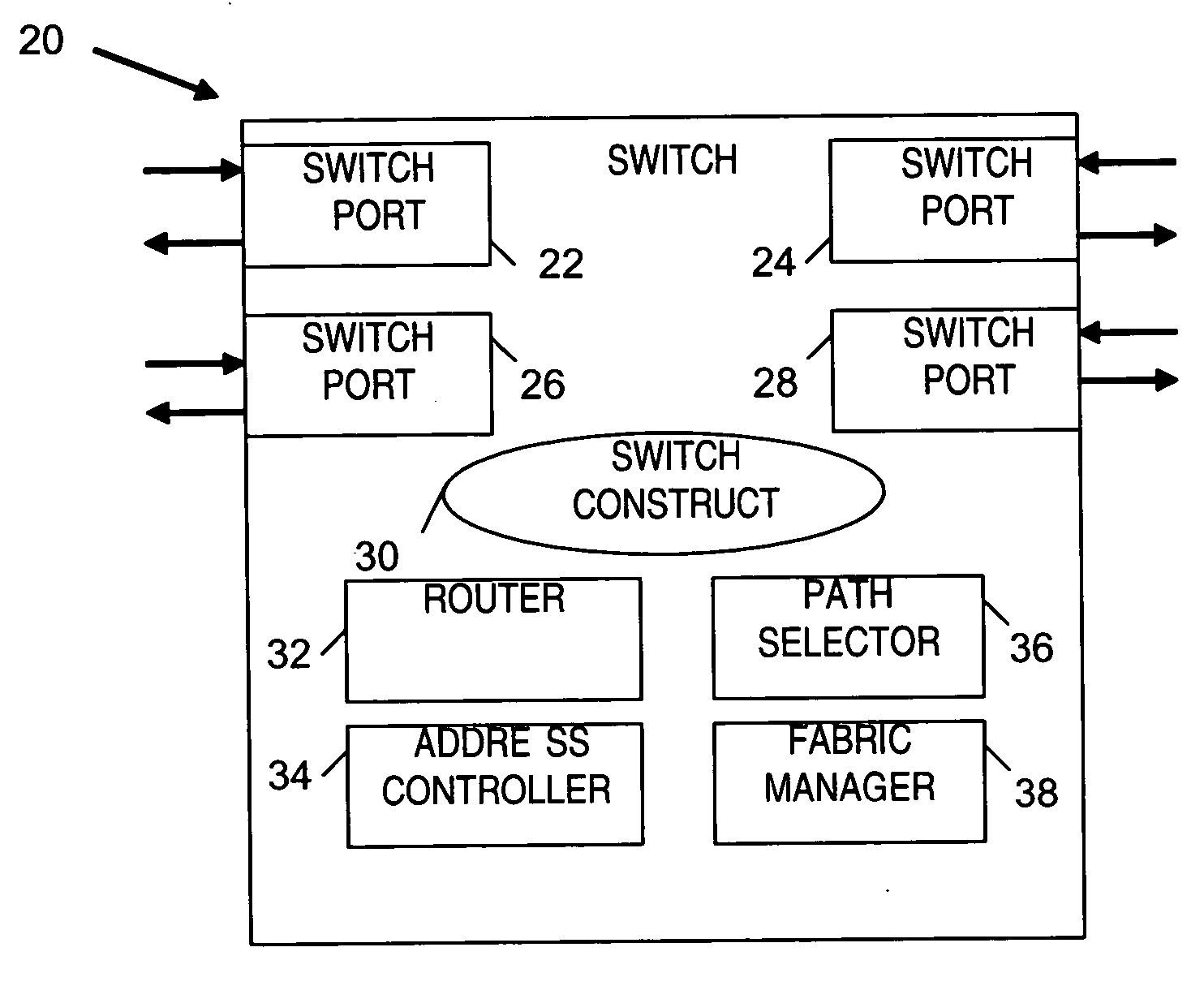
[0012] Systems and methods for gathering troubleshooting information through one or more networks are disclosed. In one embodiment, the method comprises a switch configured to receive a frame that has information added by another switch. As the frame traverses the network, control logic in the switch adds additional information into the frame from the current switch.

Problems solved by technology

Congestion and over subscription of ISLs may lead to significant performance problems due to increased latency.
Since routing within the Fibre Channel has some degree of automatic configurabilty, the actual route a particular frame takes to reach its destination becomes highly variable in large networks due to switch failures and the activation of new ISLs.
This variability may be complicated by the use of multiple, parallel ISLs between switches to form ultra-high bandwidth “trunks”.
As larger networks are implemented (e.g. more than about seven switches), troubleshooting performance drops becomes a daunting task.
For example, ISLs and ports may become congested along particular routes, significantly reducing performance.
This minimal amount of information would not really assist in troubleshooting a FC SAN.
Further, because traceroute operates by sending multiple, time-delayed packets, the returned path may actually be erroneous should the routing change in between packets.
This further limits the potential usage of a traceroute approach in a FC SAN environment.
While this technique addresses some of the problems of the traceroute approach, it still only provides minimal information and would be of minimal use in an FC environment.
Further, in an FC environment all routes are already known due to the FSPF routing protocol, so this token ring technique would be superfluous in an FC environment.

Method used


Image

  • Network path tracing method
  • Network path tracing method
  • Network path tracing method

Examples


Embodiment Construction

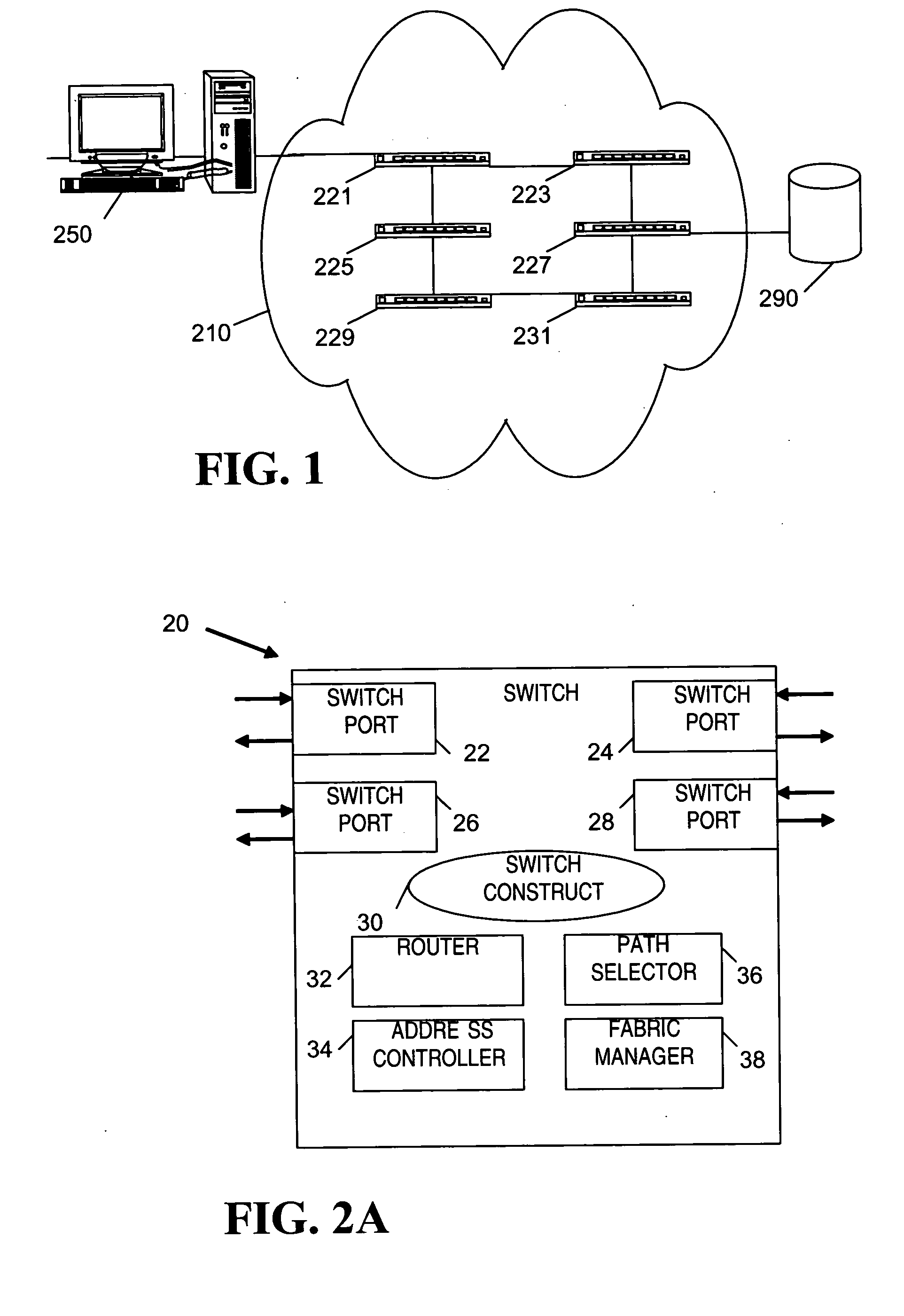
[0024]FIG. 1 shows a computer system 250 coupled to a storage device 290 by a Fibre Channel (FC) fabric 210. The computer system 250 may be any suitable node device including a desktop computer, a server, or a user terminal. Storage device 290 may similarly be any suitable node device including a JBOD (Just a Bunch of Disks), RAID (Redundant Array of Inexpensive Disks) array, tape library, or network data store. FC fabric 210 is shown having six switches 221, 223, 225, 227, 229, and 231 coupled together via inter-switch links (ISLs). The switches may have as few as two and as many as 256 or more ports. The ISLs may be oversubscribed or congested due to network traffic or faulty routing. These links also may be inactivated due to a switch failure or dynamically created if a failed switch comes back online. The preferred embodiment will help reveal these network variables by gathering information from each switch in the route of a “tracer frame”.

[0025] For exemplary purposes, a trace...


PUM


Abstract

Systems and methods for gathering troubleshooting information through one or more networks are disclosed. In one embodiment, the method comprises a switch port configured to receive a frame that has information added by another switch. As the frame traverses the network, control logic in the switch adds additional information into the frame from the current switch.

Description

RELATED CASES [0001] This application is related to U.S. patent application Ser. No. ______, entitled “Network Path Tracing Method”, by Ezio Valdevit, filed concurrently herewith.BACKGROUND [0002] Computer networks facilitate communication between computers, servers, and stand-alone peripherals. They make possible large scale computing systems, distributed service systems, and a whole host of applications that would otherwise be infeasible. Therefore, incentives exist for the use and enhancement of computer network technology. [0003] Storage area networks (SANs) are a popular type of computer network for accessing large volumes of data. A SAN is a networked infrastructure connecting servers to stand-alone data storage devices (e.g. disk drives) over a high-speed network. The SAN is usually a sub-network of a larger computer network that include servers and personal computers that need to access the data in the SAN. The advantages of SANs include having a large, shared storage capaci...

Claims


Application Information

Patent Timeline
Patent Type & Authority Applications(United States)
IPC IPC(8): H04L12/26H04L12/56
CPCH04L12/56
Inventor JUDD, JOSH
Owner AVAGO TECH INT SALES PTE LTD
Learn More