
Control and communication system and method

a communication system and control technology, applied in the field of control and information technology communication system, can solve the problems of difficult to provide protection against eventual terrorist attacks, random reports of pilots, and similar problems in shipping

Inactive Publication Date: 2005-04-28
RDS X FEJLESZTESI & TANACSADO
View PDF6 Cites 116 Cited by
  • Summary
  • Abstract
  • Description
  • Claims
  • Application Information

AI Technical Summary

Benefits of technology

[0008] It is an object of the invention to provide a system and a method for control and communication, by which the deficiencies of the prior art monitoring systems can be eliminated, and the requirements emerging can be satisfied.
[0011] Furthermore, a dynamic route planning of vehicles must be ensured in function of the current and envisaged traffic, meteorological and technical situation, as well as making it possible to forecast dangerous traffic situations also in areas not covered by radars and by auxiliary systems operated in parallel by prognosis-based calculations. In addition, by prognosis-based calculation, the forecasting of technical and human health risks must be ensured. Preferably, passengers and staff are able to use their GSM units through an on-board telephone exchange, while retaining their own telephone numbers, along with the running of an integrated health care IT communication system. Preferably, an integrated traffic control and information technology based communication system of such kind is set up as to help to provide additional (new) information for the air, water and land crew and their control centres, and also for the objects supported.
[0012] It is a further object that through the application of a system and method according to the invention, the technical-technological and logistical utilization of airports, naval ports, traffic junctions and vehicles should become more economic, the safety of transport should be enhanced, the specific environmental load should be reduced, and furthermore that the system should be compatible with the existing information technology and traffic monitoring systems. It is a further object to provide a system which is suitable for modifying the route and the traffic parameters of the route, independently from the pilot, in vehicles prepared for this task, with special regard to flying objects.
[0018] By means of the system according to the invention, control and communication meeting complex requirements and the expectations mentioned above can be implemented extremely efficiently and safely.

Problems solved by technology

The control and IT communication support of air, water and land (road and railway) transport as well as of the objects used as independent systems in numerous walks of life raise new problems as a result of a substantial increase in traffic and due to a significant growth in the control and IT communication requirements of the above mentioned objects.
However, small aircraft fly mostly over undulating terrain at an altitude and in a speed range not detected by radars, and a significant number of intercontinental flights by large aircraft are outside the radar control range.
Another disadvantage is that the existing radars are uncertain in detecting vehicles that fly at a low speed, and furthermore that reports from pilots are often random in time.
In addition, with such a concept of control, monitoring and IT communication, it is very difficult to provide protection against eventual terrorist attacks.
Under the current conditions of air traffic control, following distances between aircraft are necessarily long, and landings and takeoffs, as a result of the time factor and due to the lack of real time monitoring and control, are critical.
Similar problems arise in shipping, for example in port areas, and also in land traffic, e.g. railway transport control.
The disadvantages of this solution are that an inertial transmitter is very expensive, the relevant co-ordinate data are only known by the air crew and furthermore that each aircraft must have two of these units to ensure operational safety.
Another unfavourable feature is that it does not use current, but earlier satellite data which do not provide an up-to-date and accurate result for example at landing.
This device is based on a static co-ordinate database, which is not updated on an ongoing basis, and furthermore in this device, the road vehicles system is not built into an integrated IT network.
Due to these reasons, this solution is not suitable for implementing an aircraft traffic control system.
The drawback of this known system is the lack of provisions for a dynamic plan co-ordination, approval and updating.
Currently, no universal control system is known that would be capable of real time, automatic and long-term monitoring as well as a reliable control of objects for example aircraft and / or water and / or land vehicles by complex technical and human diagnostic supervision.
For example, the prior art traffic control devices were only able to provide spatial data within a narrow traffic zone, with subsequent data processing.
Although the photogrammetric determination of the spatial co-ordinates of vehicles as objects already exists, it is not possible to assess them in real time and to integrate them into a traffic control system.
No on-board technical and human health diagnostic device is known that can be integrated into a traffic control system for aircraft and / or water vehicles and / or land vehicles and / or staff and passengers travelling on these vehicles.
Operating GSM units above a certain speed and altitude and the application of a comprehensive health information system are currently impossible.
Furthermore, there is no control and communication system and process that could perform automatically, efficiently and in a coordinated way any local regional and central control and communication tasks generally arising in connection with objects, for example with the vehicles above and furthermore for example in connection with production and processing units, (parts of) buildings, business units or even persons.

Method used


Image

  • Control and communication system and method
  • Control and communication system and method
  • Control and communication system and method

Examples


Embodiment Construction

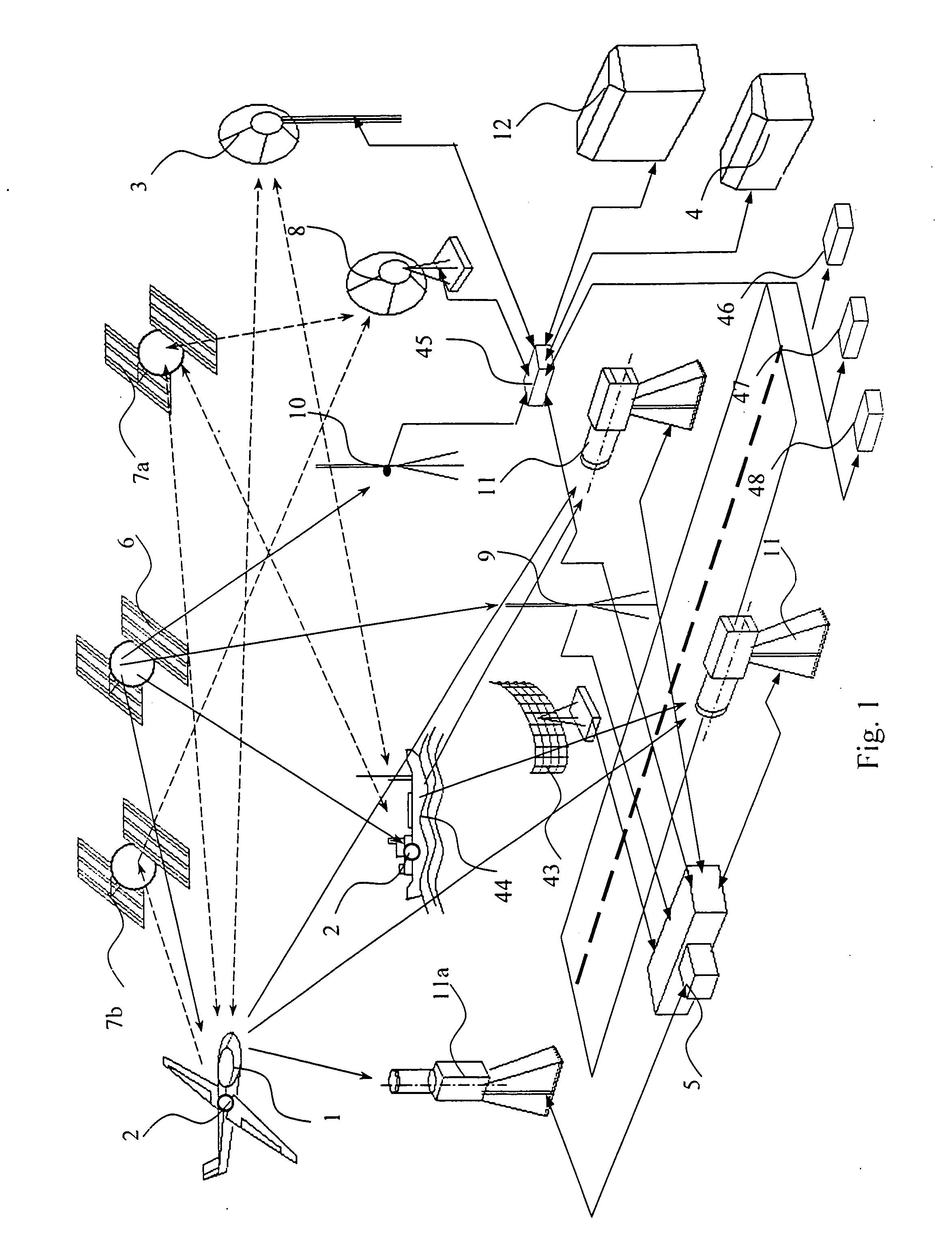
[0033] In the case of the preferred embodiments described by way of example below, the system and method according to the invention are used in traffic control, where the objects to be controlled are vehicles, and the plans to be implemented are traffic plans.

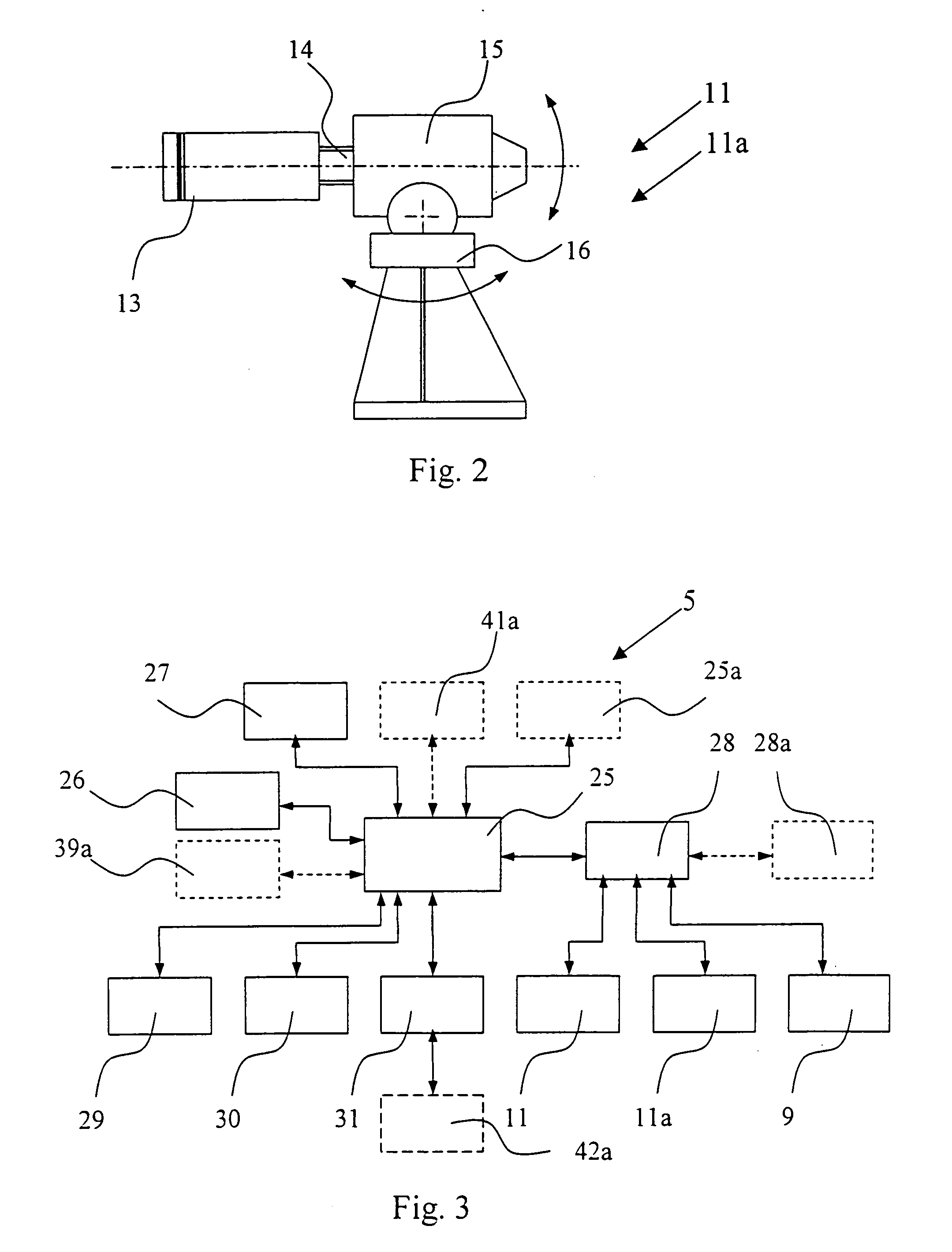
[0034] The preferred traffic control system shown by way of example in FIG. 1 performs the control of vehicles having an on-board centre as the object centre 2, for example aircraft object 1 and ship object 44. The system comprises a main control centre 12, regional control centre 4, visual processing centre 5, communication centre 45, radio re-transmitter unit 3, stationary satellite transceiver 8, re-transmitter satellite 7a, spotting satellite 7b, positioning satellite 6, regional signal improving unit 10, visual detector and identifier units II, visual identifier unit 11a, radar unit 43 and centres 46, 47 and 48 which perform various auxiliary functions. The operations of these units will be detailed below.

[0035] Visual d...


PUM


Abstract

The invention relates to a control and communication system and method for objects, the system comprising an object space-information database in an object centre of the object, the database storing an object plan for the object, wherein the control of the object is adjusted to the object plan, a regional control centre having a regional space-information database storing a regional plan, and a main control centre having a central space-information database storing a central plan. The central plan approved by the regional control centres is prepared by the main control centre, the regional plans are updated at the regional control centres on the basis of the central plan, and the object plans are updated at the object centres on the basis of the regional plans.

Description

TECHNICAL FIELD [0001] The present invention relates to a control and IT (information technology) communication system, permitting the coordinated, efficient, dynamic and automatic control and tracking of objects assigned to regions, in addition to satisfying diverse IT requirements of the objects. Furthermore, the invention is also a method for achieving the objectives above to implement control. BACKGROUND ART [0002] The control and IT communication support of air, water and land (road and railway) transport as well as of the objects used as independent systems in numerous walks of life raise new problems as a result of a substantial increase in traffic and due to a significant growth in the control and IT communication requirements of the above mentioned objects. An important area of development is small and large aircraft aviation, in which field a further growth can be predicted, as well as the provision of control and IT communication services for intelligent households. The a...

Claims


Application Information

Patent Timeline
IPC IPC(8): G08G5/00G08G7/00
CPCG08G5/0013G08G7/00G08G5/0082
Inventor BATHORY, ZSIGMONDREPASI-NAGY, LASZLO
Owner RDS X FEJLESZTESI & TANACSADO
Learn More