
Hose

a technology of hoses and hoses, applied in the field of hoses, can solve the problems of hoses falling off, water or gas leaking at a place where its pressure cannot be withstood, and prone to deformation under external force,

Inactive Publication Date: 2005-04-28
SUMITOMO YOSHIYUKI
View PDF24 Cites 16 Cited by
  • Summary
  • Abstract
  • Description
  • Claims
  • Application Information

AI Technical Summary

Benefits of technology

[0007] An object of the present invention is to provide a hose of which the fluid passage inside is not completely obstructed even when the hose is trodden on by a wheel or human or bent at an acute angle.
[0008] Another object of the present invention is to provide a hose that is resistant to deformation under an external force, that is excellent in placement stability, and that can be wound up for storage without producing dead gaps between different turns thereof, contributing to a small storage volume.
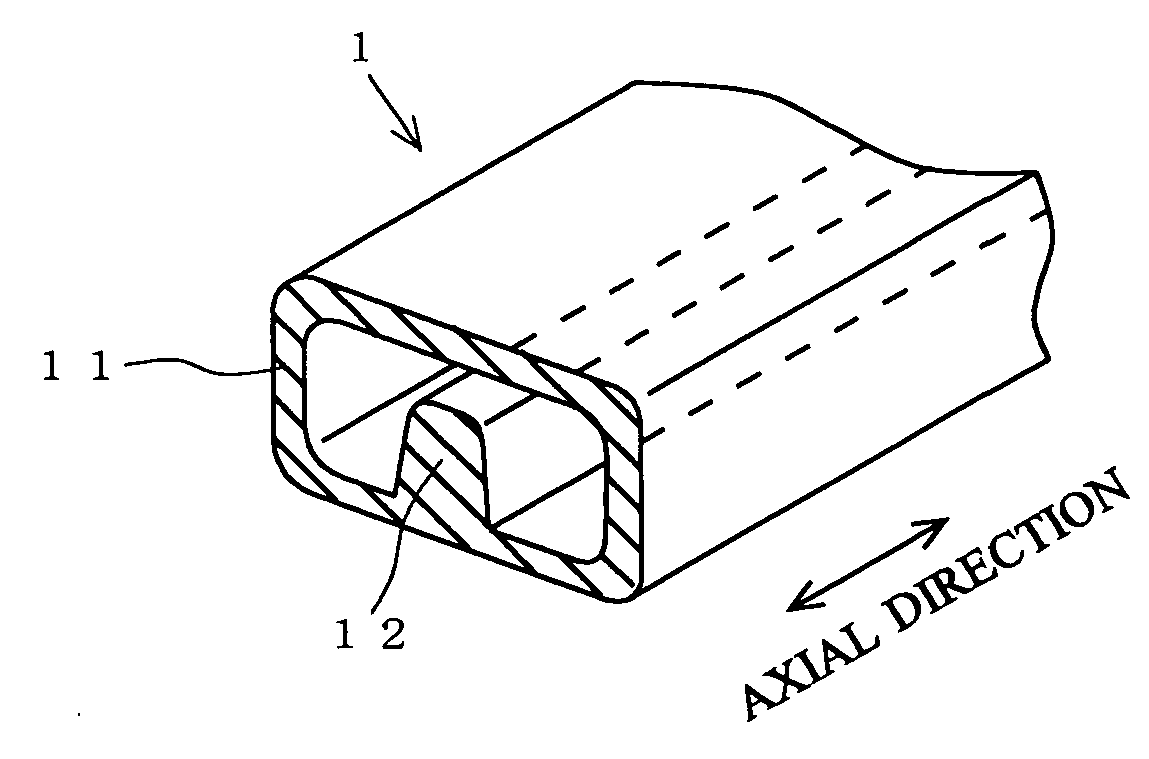
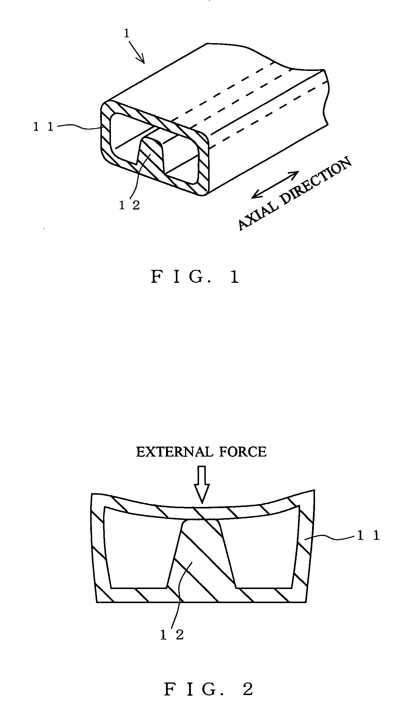
[0010] With this structure, even when the hose is trodden on by a wheel or human, or bent at an acute angle, the fluid passage inside the hose is never completely obstructed, and in addition the deformation of the hose under the external force is minimized. Moreover, since the hose body has a substantially rectangular cross-sectional external shape, when the hose is placed on a surface, it makes surface contact with the surface. This prevents the hose from being dislocated easily under a weak force, and thus contributes to excellent placement stability. Furthermore, since the hose body has a substantially rectangular cross-sectional external shape, when the hose is wound up for storage, no dead gaps are produced between different turns thereof. This helps make the storage volume smaller than for conventional hoses.
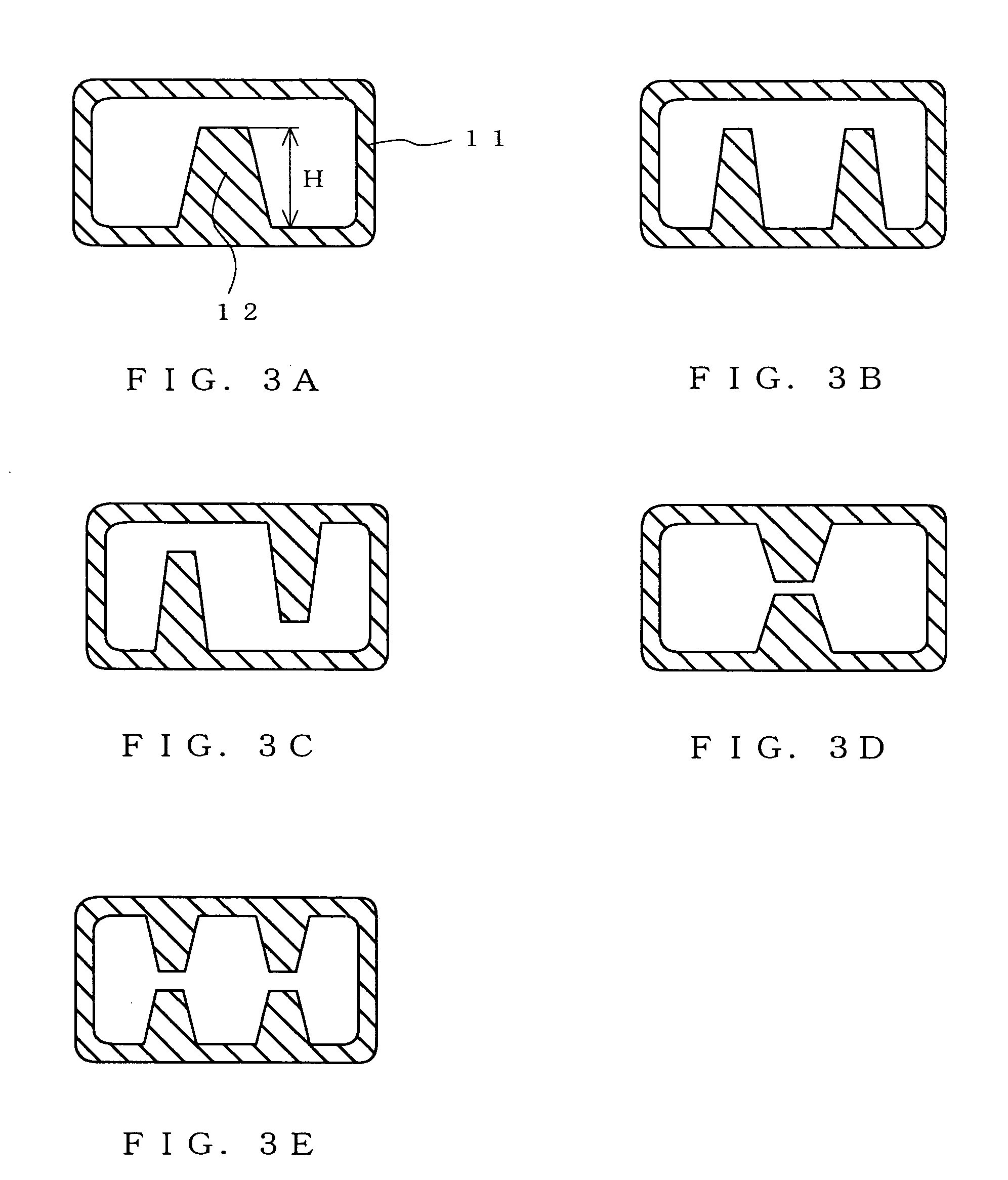
[0011] From the perspective of further reducing deformation of the hose and thereby minimizing reduction in the cross-sectional area of the fluid passage inside the hose when an external force is applied thereto, it is preferable that the linear projection be given a height equal to 50% or more of the distance from the part of the inner wall on which the linear projection is formed to the part of the inner wall opposite thereto. It should be understood that, in the present invention, the height H of the linear projection denotes the dimension from the inner wall of the hose body to the top of the linear projection (see FIG. 3A).

Problems solved by technology

This causes water or gas to leak at a place where its pressure cannot be withstood, for example where the hose is connected to a water faucet or gas outlet, or causes the hose to come off.
Moreover, a conventional hose has a circular cross section, and thus tends to be deformed greatly under an external force.
This makes it quite likely that, under a relatively weak external force, the cross-sectional area of the fluid passage inside the hose becomes, not to say completely obstructed, smaller than half the area it normally has.
This makes such a hose heavier and more expensive to produce than hoses designed for other purposes.
This results in unstable placement of the hose, allowing it to be displaced easily under a weak force.
Moreover, when the hose is wound up for storage, gaps are inevitably left between different turns thereof, resulting in an extra volume for storage.

Method used


Image

  • Hose
  • Hose
  • Hose

Examples


example 1

Practical Example 1

[0034] A hose having a cross-sectional shape as shown in FIG. 3A was produced on an extruder by using, as a material, a polyolefin-based elastomer. The longer-side and shorter-side inner dimensions of the hose were 15 mm and 8 mm, respectively; the wall thickness of the hose body was 1.5 mm; and the height of the linear projection was 6 mm. One end of this hose was connected to a faucet of tap water with a fastener, and the other end of the hose was left open. Then, the faucet was opened to let water pass through the hose, and, while the water is vigorously running out of the hose at the open end thereof, the hose, which was placed on a floor, was trodden under the feet of a person having a weight of 65 kg. Through visual checking, no variation was observed in the flow rate of the water running out of the hose at the open end thereof. Even when the hose was bent at an acute angle, no variation was observed in the flow rate of the water running out of the hose at t...


PUM


Abstract

A hose 1 has a hose body 11 of which the cross-sectional external shape as seen in a plane perpendicular to the axial direction is substantially rectangular, and has a linear projection 12 formed on the inner wall of the hose body 11 along the axial direction. To further reduce deformation of the hose 1 and thereby minimize reduction in the cross-sectional area of the fluid passage inside the hose 1 when an external force is applied thereto, the height of the linear projection 12 is preferably made equal to 50% or more of the distance from the part of the inner wall on which the linear projection 12 is formed to the part of the inner wall opposite thereto. To permit the flat wall of the hose body 11 to be supported firmly without being damaged when an external force is applied to the hose 1, the top of the linear projection 12 is preferably formed into a flat surface.

Description

BACKGROUND OF THE INVENTION [0001] 1. Field of the Invention [0002] The present invention relates to a hose for conveying fluid such as water, oil, or gas. [0003] 2. Description of the Prior Art [0004] A conventional hose designed for household use for conveying fluid such as water, oil, or gas is typically made of rubber for its easy handling and usability. When used, such a hose is so placed as to lie on a table, floor, or ground. Thus, for example as shown in FIGS. 5A and 5B, when the hose is trodden on by a human or wheel (FIG. 5A), or when it is caught at a corner of an object and thereby bent at an acute angle (FIG. 5B), the fluid passage inside the hose is obstructed at that place. This causes water or gas to leak at a place where its pressure cannot be withstood, for example where the hose is connected to a water faucet or gas outlet, or causes the hose to come off. [0005] Moreover, a conventional hose has a circular cross section, and thus tends to be deformed greatly under...

Claims


Application Information

Patent Timeline
IPC IPC(8): F16L11/12F16L11/22
CPCF16L11/22F16L11/121
Inventor SUMITOMO, YOSHIYUKI
Owner SUMITOMO YOSHIYUKI
Learn More