Metal coordination compound and electroluminescence device
a technology of electroluminescence and metal coordination compound, which is applied in the field of electroluminescence devices, can solve the problems of device utilizing phosphorescence described above accompanied by a problem regarding luminescence deterioration and device is problematic in terms of deterioration in energized state, and achieves high luminance or brightness and high efficiency. luminescence
- Summary
- Abstract
- Description
- Claims
- Application Information
AI Technical Summary
Benefits of technology
Problems solved by technology
Method used
Image
Examples
example 1
Synthesis of Example Compound No. 1
[0073]
[0074] In a 2 L (liter)-three-necked flask, 69.0 g (472 mM) of α-tetralone, 50.0 g (720 mM) of hydroxylamine hydrochloride, 500 ml of ethanol and 360 ml of 2N-sodium hydroxide aqueous solution were placed and stirred for 1 hour at room temperature. The solvent was removed under reduced pressure to provide a dry solid (residue). To the residue, 500 ml of water was added and extracted three times with 150 ml of ethyl acetate. The organic layer was dried with anhydrous magnesium sulfate, followed by removal of the solvent under reduced pressure to obtain 74 g (Yield: 97.2%) of a pale yellow crystal of α-tetralone=oxime.
[0075] In a 1 L-three-necked flask, 80 ml of tetrahydrofuran and 23.8 g (595 M) of 60%-oily sodium hydride were placed and stirred for 5 minutes at room temperature, followed by addition thereof dropwise to solution of 74.0 g (459 mM) of α-tetralone=oxime in 500 ml of anhydrous DMF (dimethylformamide) in 15 minutes. Thereafter, ...
example 2
Synthesis of Ex. Comp. No. 53
[0079]
[0080] In a 3 L (liter)-three-necked flask, 166.0 g (1036 mM) of 1-benzosuberone, 125.0 g (1141 mM) of O-allylhydroxylamine hydrochloride, 93.5 g (1140 mM) of sodium acetate, 158.0 g (1143 mM) of potassium carbonate and 1500 ml of ethanol were placed and stirred for 1.5 hours at 80° C. under heating. The reaction product was cooled to room temperature and subjected to removal of the solvent under reduced pressure to obtain a residue. To the residue, 1500 ml of water was added and extracted three times with 500 ml of ethyl acetate. The organic layer was dried with anhydrous magnesium sulfate and subjected to removal of the solvent under reduced pressure to obtain a pale brown liquid. The liquid was subjected to distilling-off of the solvent under reduced pressure to obtain 221.8 g (Yield: 99.0%) of 1-benzosuberone=oxime=O-allyl=ether having a boiling agent of 75-83° C. (4.0 Pa).
[0081] In a 5 L-autoclave, 222.0 g (1022 mM) of 1-benzosuberone=oxime=...
example 12
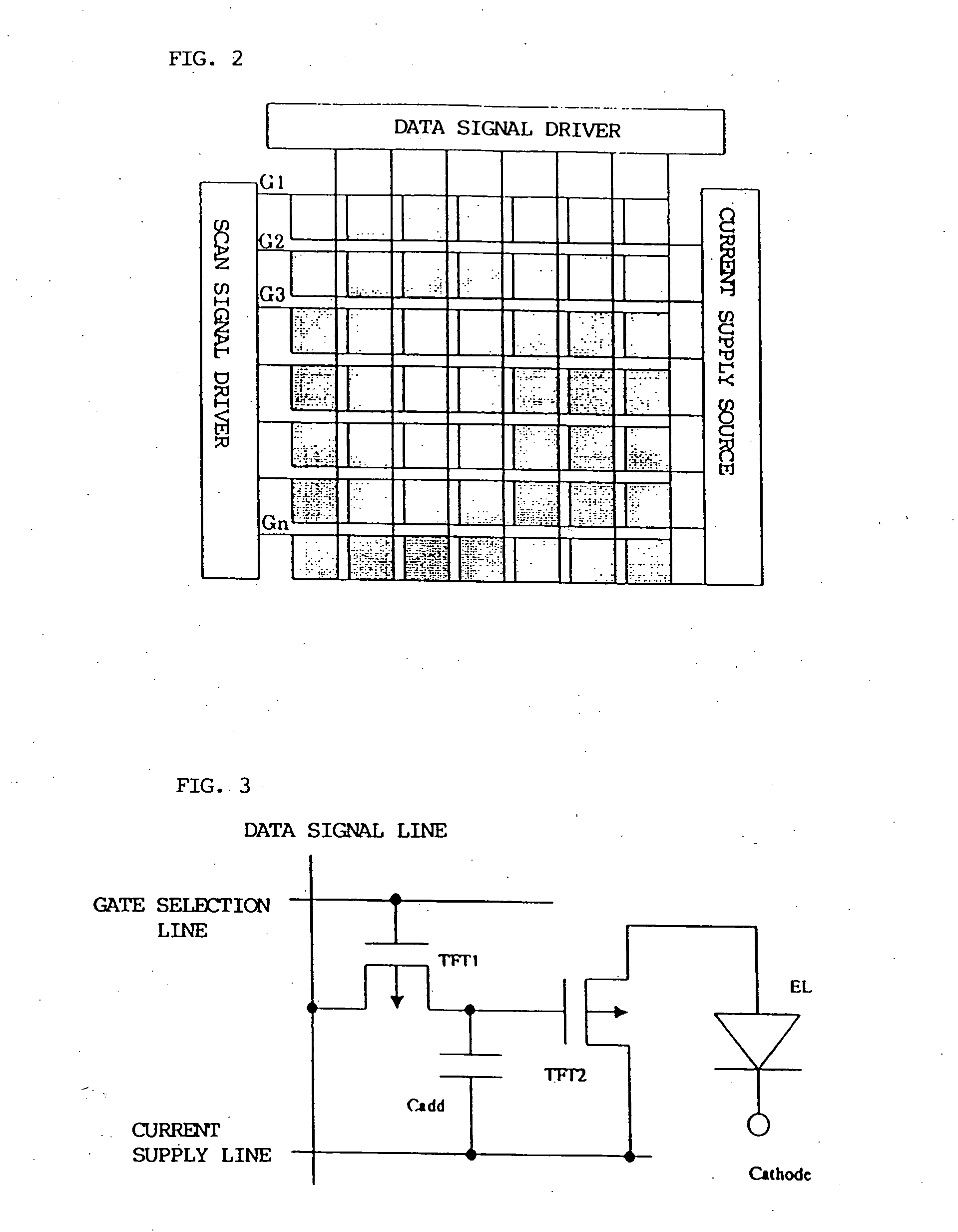
[0096] An embodiment of the electroluminescence device of the present invention applied to an active-matrix type color organic EL display using a TFT circuit shown in FIG. 3 will be described with reference to FIG. 2.
[0097]FIG. 2 schematically illustrates an example of a panel structure provided with an organic EL device and drive means. In this example, the number of pixels was set to 128×128 pixels. Incidentally, one pixel was composed of three color pixels comprising a green pixel, a blue pixel and a red pixel.
[0098] On a glass substrate, a thin film transistor circuit using polysilicon (referred to as a TFT circuit) was formed by a known method.
[0099] In regions corresponding to the respective color pixels, organic layers and a metal electrode layer were formed in the following thicknesses by vacuum deposition with a hand mask, followed by patterning. Organic layer structures corresponding to the respective color pixels are shown below. [0100] Green pixel=α-NPD (40 nm) / CBP:ph...
PUM
| Property | Measurement | Unit |
|---|---|---|
| excitation wavelength | aaaaa | aaaaa |
| Yield | aaaaa | aaaaa |
| Yield | aaaaa | aaaaa |
Abstract
Description
Claims
Application Information
 - R&D
- Intellectual Property
- Life Sciences
- Materials
- Tech Scout
- Unparalleled Data Quality
- Higher Quality Content
- 60% Fewer Hallucinations
Browse by: Latest US Patents, China's latest patents, Technical Efficacy Thesaurus, Application Domain, Technology Topic, Popular Technical Reports.
© 2025 PatSnap. All rights reserved.Legal|Privacy policy|Modern Slavery Act Transparency Statement|Sitemap|About US| Contact US: help@patsnap.com


