Non-imaging optical corner turner

Inactive Publication Date: 2005-04-21
TYCO HEALTHCARE GRP LP
View PDF18 Cites 17 Cited by
  • Summary
  • Abstract
  • Description
  • Claims
  • Application Information

AI Technical Summary

Benefits of technology

[0014] The present invention provides a device and method to efficiently turn light from an optical fiber around a corner that would cause excessive light loss, by failure of TIR, if the fiber were bent. The invention uses non-imaging optics which efficiently deal with divergence half-angles less than 90°. By recognizing that most light from a fiber optic source will have a divergence half-angle of less than 90 degrees, a practical solution is achieved using non-imaging optics.
[0021] In an alternate embodiment, two CPCs can be used, with an elliptical reflector on the inside turn of the corner, and another elliptical segment reflector on the outside turn. Alternately, the inside turn could be eliminated by joining one edge of the incoming fiber optic to an edge of the outgoing fiber optic.

Problems solved by technology

An optical fiber cannot be bent around a sharp angle because it will break and it will lose light because some of the light rays it is carrying will strike the cladding at less than the critical angle.
When this occurs, the efficiency of transmission is significantly reduced.
One reason for this is that the patient might be burned by the wires during the procedure, since the high electromagnetic fields of the MRI instrument can induce high currents in the wires.
There are prior art optical devices which can achieve efficient corner turning but they use imaging optics and tend to be expensive and bulky.
Other prior art corner turning devices often require high Numerical Aperture (NA) imaging optics and tend to be expensive and lossy.
As such, this use of the toroid is inefficient, which is to say that it does not minimize étendue of the output beam (étendue is defined, in the 2D case, as the product of NA and the beam diameter).

Method used


Image

  • Non-imaging optical corner turner
  • Non-imaging optical corner turner
  • Non-imaging optical corner turner

Examples


Embodiment Construction

I. Set-up of the Problem:

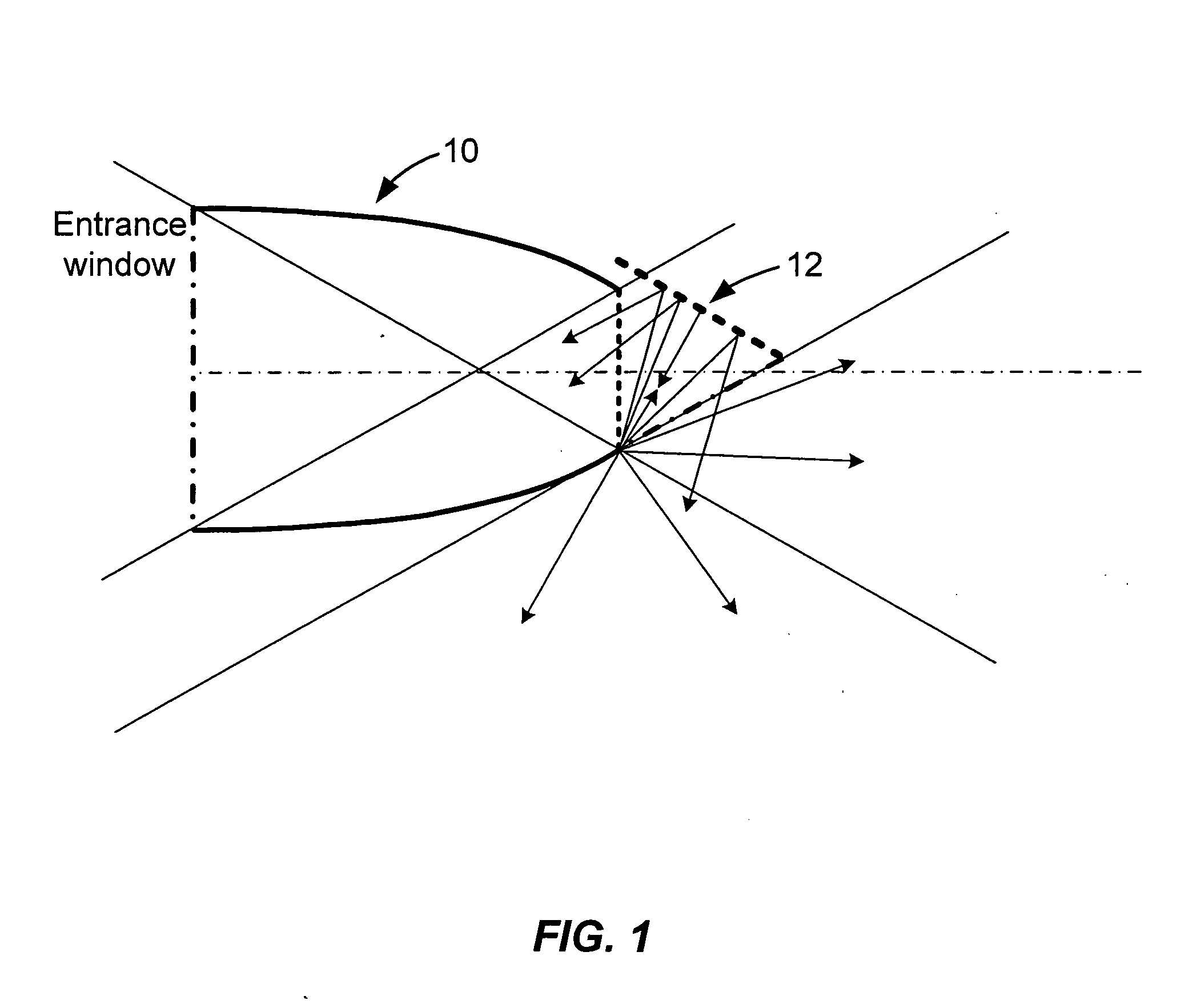
[0043]FIG. 1 shows an air-filled, two-dimensional, compound parabolic concentrator (2D CPC) 10, designed to accept rays at up to 30 degrees from the system axis (i.e., NA=0.5). As used herein, φ is defined as the maximum angle which a propagating ray may bear to the optical axis of input and output channels, θ is defined as the angle through which the corner turner rotates the optical axis, and the Numerical Aperture (NA) is defined as product of the sin of φ and the refractive index, n, of the medium in which light propagates. The examples presented herein are worked out for a medium with n=1 (i.e. air). For cases in which the medium of propagation has higher refractive index, e.g. for corner turners molded of solid plastic or glass, it is straightforward to calculate the appropriate value of φ if the NA of propagating light is known, as it commonly will be in the design of an optical system. At the exit surface of the CPC of FIG. 1, the rays have been conc...


PUM


Abstract

The present invention provides a device and method to efficiently turn light from an optical fiber around a corner while avoiding the frustrated-TIR loss that would occur if the fiber were bent. The invention uses non-imaging optics which efficiently deal with beam divergence half-angles less than 90°. By recognizing that most light from a fiber optic source will have a divergence half-angle of less than 90 degrees, a practical solution is achieved using non-imaging optics.

Description

FIELD OF THE INVENTION [0001] The present invention relates to a device that changes the direction of a beam of light in a non-imaging application (i.e. an application in which the primary concern is to transport optical energy efficiently, with minimal loss of brightness, rather than to preserve an image). The device is particularly useful in changing the direction of light that is carried by optical fibers, although it may also be useful in any optical system requiring the redirection of a light beam. Examples of such systems are solid optical waveguide structures on planar substrates, hollow optical waveguide structures (such as those commonly used in carrying infrared laser beams for surgical applications) and systems using relay lenses, in which the light beam travels primarily in air rather than in a solid material. BACKGROUND OF THE INVENTION [0002] An optical fiber cannot be bent around a sharp angle because it will break and it will lose light because some of the light rays...

Claims


Application Information

Patent Timeline
IPC IPC(8): G02B6/10G02B6/26G02B17/06H01S3/30
CPCG01N2021/3144G02B6/102G02B6/262G02B19/0033G02B19/0019G02B19/0023G02B6/32
Inventor FEIN, MICHAEL
Owner TYCO HEALTHCARE GRP LP
Why Eureka
Try Eureka