
Lineraly polarized light separating film, linearly polarized light separating laminate film, backlight system and liquid crystal display

a technology of linear polarization and light separating film, which is applied in the direction of polarising elements, instruments, projectors, etc., can solve the problems of whitening or cloudiness, defect in display of liquid crystal displays, and linear polarized light separating films (b>1/b>) have another problem, so as to achieve softening of film or charge, good handling

Inactive Publication Date: 2005-04-21
NITTO DENKO CORP
View PDF9 Cites 25 Cited by
  • Summary
  • Abstract
  • Description
  • Claims
  • Application Information

AI Technical Summary

Benefits of technology

[0009] It is an object of the present invention to provide a linearly polarized light separating film good in scratch resistance. It is another object of this invention to provide a linearly polarized light separating film good in scratch resistance and excellent in handleability.
[0010] It is still another object of the present invention to provide a conductive linearly polarized light separating film having an antistatic effect, and excellent in durability together with the above described characteristics.
[0014] In the present invention, a scratch resistance can be imparted to the linearly polarized light separating film by formation of the hard coat layer. The hard coat layer can be formed as a coat good in scratch resistance even in heating. Such a hard coat layer can be imparted with a hardness to prevent deformation of the surface in heating. The hard coat layer can impart durability in a humidified state. Since a linearly polarized light separating film of this invention has, in this way, a hard coat layer, a scratch caused by a prism sheet (light condensing sheet) can be prevented even in heating test or the like.
[0015] In the linearly polarized light separating film, a thickness of the hard coat layer is preferably in the range of from 1 to 6 μm. A linearly polarized light separating film of the present invention can be imparted with scratch resistance by the hard coat layer, whereas a problem occurs that the linearly polarized light separating film is easy to be torn along a transverse direction in which stretching is applied due to formation of the hard coat layer. When a linearly polarized light separating film on which the hard coat layer is formed is bent with the hard coat layer located on the outer side (on the convex side), a problem arises that cracking occurs in the hard coat layer with ease. Since with decrease in the bending radius, breakage occurs in the linearly polarized light separating film, handleability is insufficient. Such a problem is solved in this invention by adopting a hard coat layer having a thickness in the range of 1 to 6 μm. With a thickness of the hard coat layer controlled in the range, generation of cracking in the hard coat layer can be prevented even in a case where the linearly polarized light separating film is bent. Furthermore, breakage of the linearly polarized light separating film can be prevented. A linearly polarized light separating film of this invention is in this way excellent in bendability and handleability. If a thickness of the hard coat layer exceeds 6 μm, an effect of the hard coat layer is enhanced, whereas bendability is lowered to thereby generate cracking with ease when being bent. On the other hand, if a thickness of the hard coat layer is less than 1 μm, bendability is good, while the effect of the hard coat layer is weakened (a pencil hardness and scratch resistance are reduced). In order to achieve compatibility between a hardness and bendability of the hard coat layer, a thickness of a hard coat layer is in the range of from 1 to 6 μm and preferably in the range of from 1.5 to 4 μm.
[0016] A linearly polarized light separating film of the present invention preferably generates no cracking in a hard coat layer even in a case where the film is wound on a rod having a circular section of a diameter of 6 mm with the hard coat layer located on the outer side as convex side. This shows a good bendability of the linearly polarized light separating film.
[0025] A linearly polarized light separating film of the present invention is good in handleability and can be used by laminating a linearly polarizing film and in addition, an optical element such as a retardation plate and others thereon. Since a linearly polarized light separating film of this invention has a hard coat layer and in addition, a conductive hard coat layer, the film can be used for brightness enhancement in a backlight system or a liquid crystal display without degrading a display quality on a liquid crystal panel because of softening of the film or charge therein.

Problems solved by technology

The linearly polarized light separating film (1) has another problem.
Ionic materials such as a cationic material and an anionic material used as an antistatic agent in the published patent application has a great influence on a conductivity in a humidified condition and unstable, and in addition, has a poor durability in a humidified environment at 60° C. and 90% R.H., for example, which has led a problem to easily cause whitening or cloudiness.
As a result, in an ordinary liquid crystal display, the linearly polarized light separating film (1) is easily deformed on the surface thereof by being brought into contact with a light condensing film used ordinarily and the deformation has led to a problem to generate a defect in display of a liquid crystal display.
The antistatic agent layer of JP-A No 2003-207633 has not solved such a problem.

Method used


Image

  • Lineraly polarized light separating film, linearly polarized light separating laminate film, backlight system and liquid crystal display
  • Lineraly polarized light separating film, linearly polarized light separating laminate film, backlight system and liquid crystal display
  • Lineraly polarized light separating film, linearly polarized light separating laminate film, backlight system and liquid crystal display

Examples


example 1

[0082] DBEF manufactured by 3 M Co. was used as a linearly polarized light separating functional film. Coated on one side of DBEF was a coating liquid having a solid matter concentration of 25 wt % obtained by dispersing an acrylic-based hard coat resin (manufactured by DAINIPPON INK & CHEMICALS, Inc. with a trade name of UNIDIC 17-813) in isopropyl alcohol, and the wet coat was dried at 80° C. for 2 min and subjected to an ultraviolet treatment to thereby form a hard coat layer of 1.5 μm in thickness and obtain a linearly polarized light separating film.

examples 2 to 6

[0083] A linearly polarized light separating film was obtained by forming a hard coat layer in a similar way to that in Example 1 with the exception that in Example 1, a thickness of the hard coat layer was changed as shown in Table 1.

example 7

[0085] DBEF manufactured by 3 M Co. was used as a linearly polarized light separating functional film. Coated on one side of DBEF was a coating liquid having a solid matter concentration of 25 wt % obtained by dispersing 30 parts by weight of metal fine particles (ATO: antimony containing tin oxide with an average particle diameter of 40 nm or less) and 70 parts by weight of an acrylic-based hard coat resin (manufactured by DAINIPPON INK & CHEMICALS, Inc. with a trade name of UNIDIC 17-813) in isopropyl alcohol, and the wet coat was dried at 80° C. for 2 min and subjected to an ultraviolet treatment to thereby form a conductive hard coat layer of 2.5 μm in thickness and obtain a linearly polarized light separating film.


PUM

PropertyMeasurementUnit
thicknessaaaaaaaaaa
diameteraaaaaaaaaa
transmittanceaaaaaaaaaa

Abstract

A linearly polarized light separating film comprising a linearly polarized light separating film and a hard coat layer, which is preferably a thickness in the range of from 1 to 6 μm, which is preferably formed with a resin coat layer having conductivity in which metal oxide fine particles are dispersed, on one side thereof, is good in scratch resistance, and in handleability.

Description

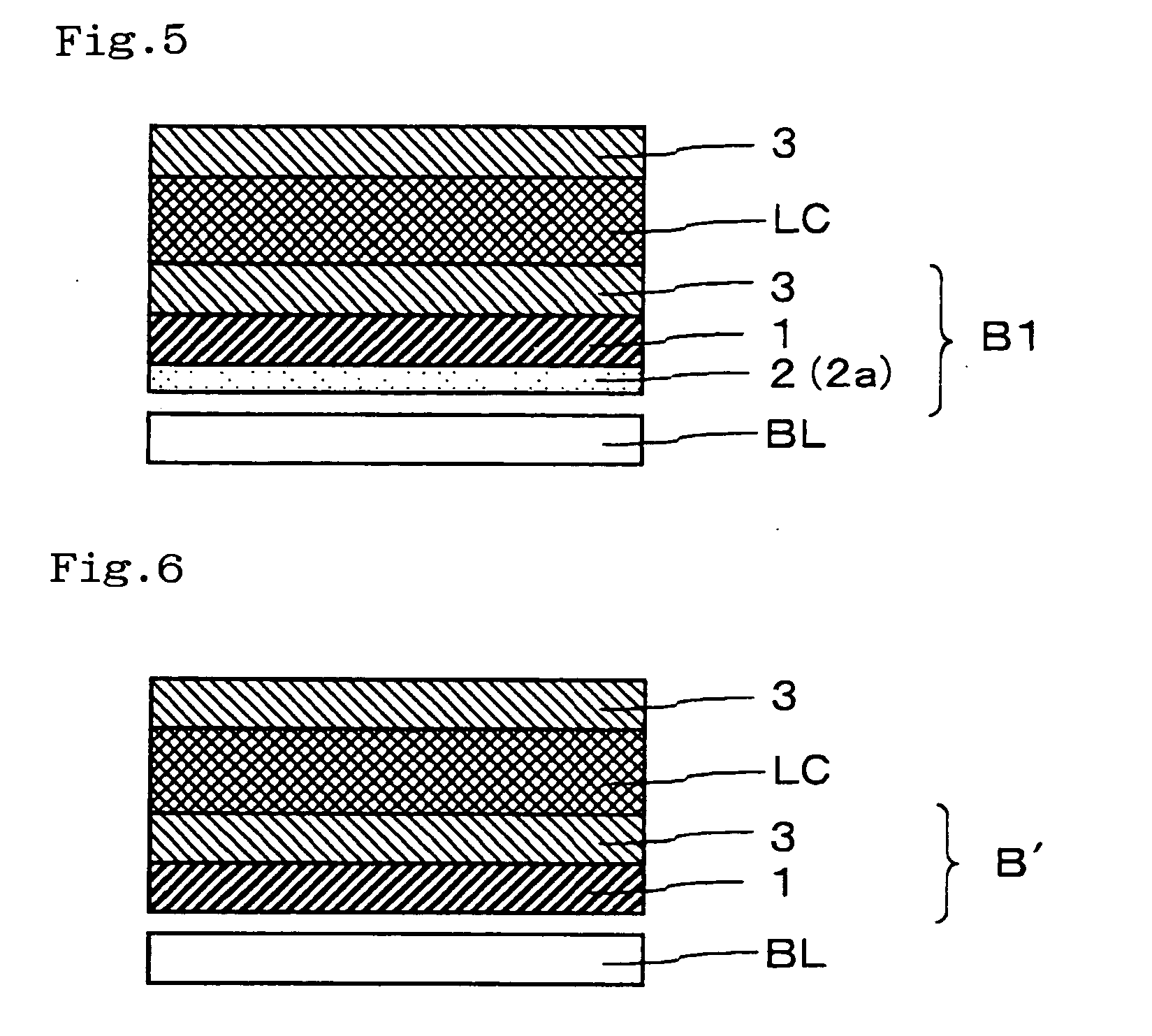
BACKGROUND OF THE INVENTION [0001] 1. Field of the Invention [0002] The present invention relates to a linearly polarized light separating film suitable for an image display such as a liquid crystal display. The present invention further relates to a linearly polarized light separating laminate film laminating the linearly polarized light separating film and a linearly polarizing film. The present invention still further relates to a backlight system and to a liquid crystal display, which using the linearly polarized light separating film and the linearly polarized light separating laminate film. [0003] 2. Description of the Background Art [0004] A linearly polarized light separating laminate film (B′) obtained, as shown in FIG. 4, by laminating a linearly polarized light separating film (1) and a linearly polarizing film (3) to each other is an optical element used in a state of being adhered to a liquid crystal cell in a transmission type liquid crystal display or the like. The li...

Claims


Application Information

Patent Timeline
Patent Type & Authority Applications(United States)
IPC IPC(8): G02B1/10G02B5/30G02F1/1335G02F1/13357G02F1/13363
CPCG02B5/305G02F1/1335
Inventor MOTOMURA, HIRONORIKANATANI, MINORUTAKAO, HIROYUKI
Owner NITTO DENKO CORP
Learn More