Multiple format magnetic storage media drive

a magnetic storage media and multi-format technology, applied in the field of magnetic tape storage devices and systems, can solve the problems of static shift, unrepeatability, and increased risk of error in the tape, so as to achieve stable and reliable recording, stable recording, and stable recording.

Inactive Publication Date: 2005-04-21
QUANTUM CORP
View PDF35 Cites 6 Cited by
  • Summary
  • Abstract
  • Description
  • Claims
  • Application Information

AI Technical Summary

Problems solved by technology

The tape therefore becomes more susceptible to errors caused from the tape shifting up or down (called lateral tape motion or “LTM”) in a direction perpendicular to the tape travel path as the tape passes by the magnetic head.
Some may cause abrupt momentary jumps while others may cause a static shift.
Generally, LTM is unpredictable and unrepeatable.
In multi-head, multi-channel magnetic tape storage systems, random lateral tape motion is generally a limiting factor in achieving higher track densities and thus higher user data capacity per tape.
Miss-registration between the head and the data track can cause data errors during readback and data loss on adjacent tracks during writing.

Method used


Image

  • Multiple format magnetic storage media drive
  • Multiple format magnetic storage media drive
  • Multiple format magnetic storage media drive

Examples


example i

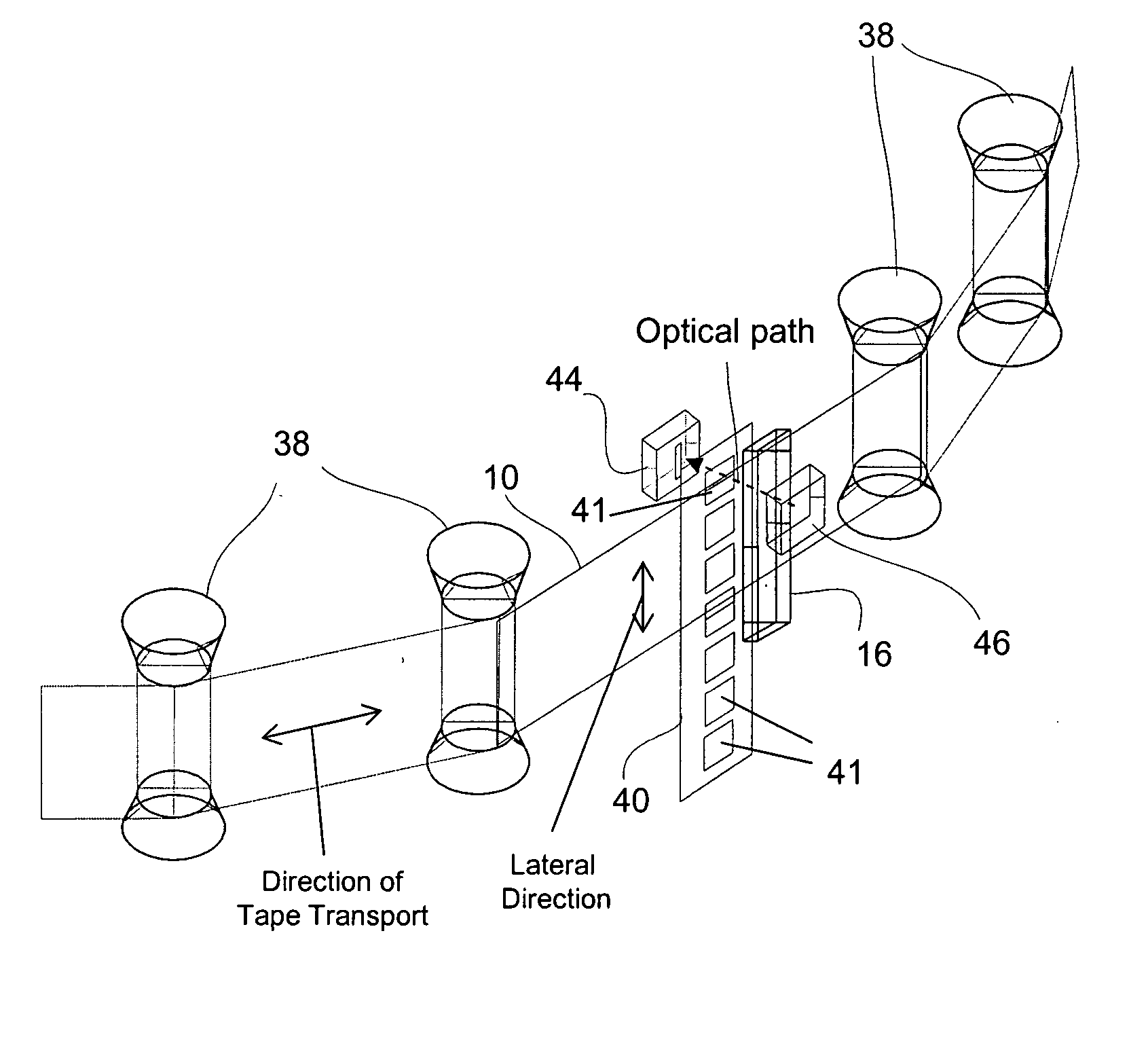
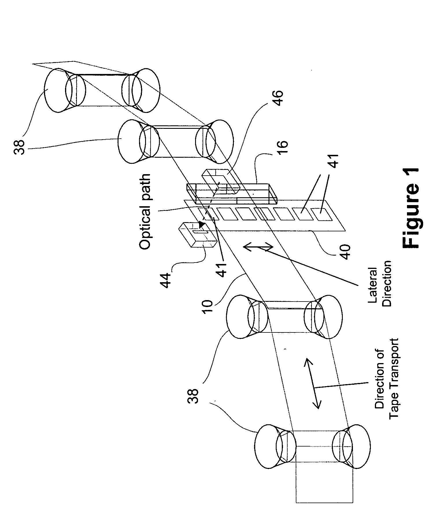
[0045] To test the feasibility of using a tape edge sensor and track the LTM of a storage tape, an optical servo system including a transmissive optical sensing device similar to that shown in FIG. 1 was attached to an SDLT220 drive, manufactured by Quantum Corporation. The sensing device was positioned such that it monitored the position of the top edge of the tape relative to the position of the read / write head. The gain and offset of the accompanying electronic circuitry were set so that an analog signal was generated with a range of 0 to 3 volts that corresponded to approximately five 24-micron wide SDLT220 format data tracks. The analog signal was used as an input to an A / D converter on the SDLT220 tape drive. Each 0.6 volt change in signal (44 out of 256 A / D bits) represented approximately 24 microns.

[0046] The tape edge sensor signal was calibrated and suitable firmware was written for the SDLT220 to test the ability to track to the tape edge sensor. Two conditions were test...

example ii

[0095] In one example of the above method, firmware was written for a SDLT220 tape drive manufactured by Quantum Corporation. The firmware utilized the optical tracking servo system of the SDLT220 with “assistance” from reading the edge of an adjacent reference track. A Read Gate signal is generated by the SDLT220 read channel that indicates whether the read channel has read a good block of data. If the Read Gate signal is greater than a predetermined value, then the data block was good. Conversely, if the Read Gate signal is below the predetermined value, then the data block was bad.

[0096] Several data tracks were written in standard SDLT220 mode. The data tracks were then read. After the SDLT220 optical servo locked the head onto the center of a data track, the Read Gate signal was sampled by the servo system at a frequency of 10 KHz for 7.5 milliseconds. If the majority of the samples were good, then an offset was added to the current optical servo position to move the head fart...


PUM

PropertyMeasurementUnit
diameteraaaaaaaaaa
diameteraaaaaaaaaa
frequencyaaaaaaaaaa

Abstract

Methods and systems are provided for receiving and streaming storage tape by a tape head from storage tape cartridges of varying formats in a single tape drive. In one example, an exemplary tape drive system includes a receiver, a reel driver system configured to selectively drive at least two cartridges having different cartridge formats, and a drive leader system configured to selectively couple with at least two different cartridge leader formats associated with the at least two different cartridge formats.

Description

CROSS REFERENCE TO RELATED APPLICATION [0001] The present application is related to earlier filed provisional patent application, U.S. Application No. 60 / 513,156, filed on Oct. 20, 2003, and entitled “SERVO METHODS AND SYSTEMS FOR MAGNETIC RECORDING AND READING,” which is hereby incorporated by reference as if fully set forth herein.BACKGROUND [0002] 1. Field of the Invention [0003] The invention and its various aspects relate generally to magnetic tape storage devices and systems, and more particularly to methods and systems for receiving and driving storage cartridges of varying formats, and for head positioning servo systems for aligning a read / write head with storage cartridges of varying formats. [0004] 2. Description of the Related Art[0005] Digital tape-recording remains a viable solution for storage of large amounts of data. Conventionally, at least two approaches are employed for recording digital information onto magnetic recording tape. One approach calls for moving a mag...

Claims


Application Information

Patent Timeline
Patent Type & Authority Applications(United States)
IPC IPC(8): G11B15/67G11B23/107G11B25/06
CPCG11B25/066G11B15/673
Inventor SALIBA, GEORGE A.COLES, VERNON P.
Owner QUANTUM CORP
Why Eureka
Try Eureka