
Enhancement of barrier fabrics with breathable films and of face masks and filters with novel fluorochemical electret reinforcing treatment

Inactive Publication Date: 2005-04-14
TENNESSEE RES FOUND INC UNIV OF
View PDF11 Cites 146 Cited by
  • Summary
  • Abstract
  • Description
  • Claims
  • Application Information

AI Technical Summary

Benefits of technology

Nonwoven webs (fabrics) are defined as “sheet” or web structures made by bonding and / or interlocking fibers, yarns or filaments by mechanical, thermal, chemical or solvent means.” These webs do not require the conversion of fibers to yarn. Nonwoven webs are also called bonded or engineered webs and are manufactured by processes other than spinning, weaving or knitting, hence the name “nonwovens.” The basic structure of all nonwovens is a web of fibers or filaments. A single type of fiber or filament may be the basic element of a nonwoven. Fibers that measured in centimeters or inches or fractions thereof are called staple fibers. In general filament fibers are measured in terms of kilometers or miles. In fact, filament fibers are not readily measured, as they may be many, many yards in length. In fibers the length must be considerably greater than the diameter, e.g., a length-to-width ratio of at least 100 and usually considerably higher. Cotton fibers may measure from less than ½ inch (o.27 cm) to more than 2 inches (5.08 cm) in length and have a typical length-to-width ratio of about 1400. Other natural fibers exhibit diameter ratios as follows: flax—1200; ramie—3000; and wool—3000. In the present application, the terms “fiber” or “fibers” are intended to include both short and long fibers, i.e. staple fibers and filament fibers, unless otherwise, specifically indicated by identifying the fibers as staple or filament. For example, spunbonded webs are formed of filament fibers, whereas, melt blown webs may include an assortment of fiber lengths. In nonwovens, the individual fibers may be in an organized or in a random arrangement. Tensile, elongation, and hand properties are imparted to the web by the type or types of bonding as well as fiber-to-fiber cohesion and reinforcement by its constituents. The technology for making nonwoven webs is based on the following primary elements: fibers of various lengths and diameters; a web arranged according to the method of forming and processing; the bonding of fibers within the web and reinforcement by its constituents. The variation of one or several elements in combination allows for the enormous range of nonwoven fiber types. Control of the type and length of the fibers and of the bonding, in combination with the selection of the manufacturing method, gives rise to a highly technical, yet extremely flexible combination of options.
Traditionally, surgical gowns have been used by health care providers to ensure that patients do not contract any infection while receiving quality care in a hospital. The possibility of the health provider becoming infected by Human Immunodeficiency (HIV), Hepatitis B viruses (HBV) (“Facts and Fiction about Single-Use and Reusable Drapes and Gowns,” Brochure from INDA, Association of the Nonwovens Fabrics Industry, Cary, N.C., 1993; “How OSHA Regulations on Bloodborne Pathogens Protect you from AIDS and Hepatis,” Brochure from INDA, Cary, N.C., 1993) and more recently to Severe Acute Respiratory Syndrome (SARS) virus, as well as the threat of pathogens being spread by biological warfare and terrorism, has resulted in much increased concern for the safety of the health-care giver or the emergency responder, as well.

Problems solved by technology

Nevertheless, the face mask laminates may be thermally or ultrasonically bonding together by a “spot welding” technique which does not fuse enough of the laminate together to excessively increase the pressure drop across the filter and make it difficult for one to breathe easily through the fabric, or to cause pin hole to form in the laminate and increase the risk of harmful particles through the face mask.

Method used

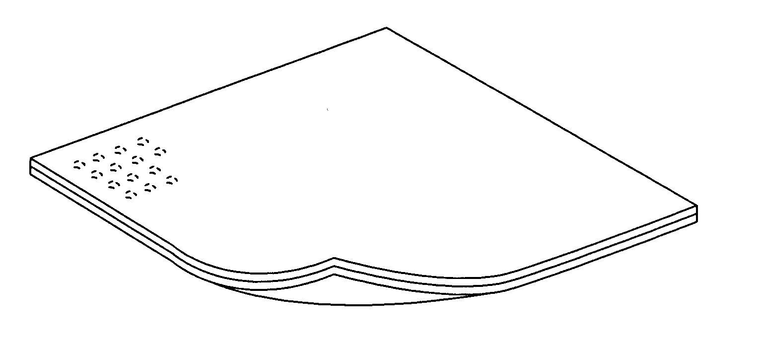
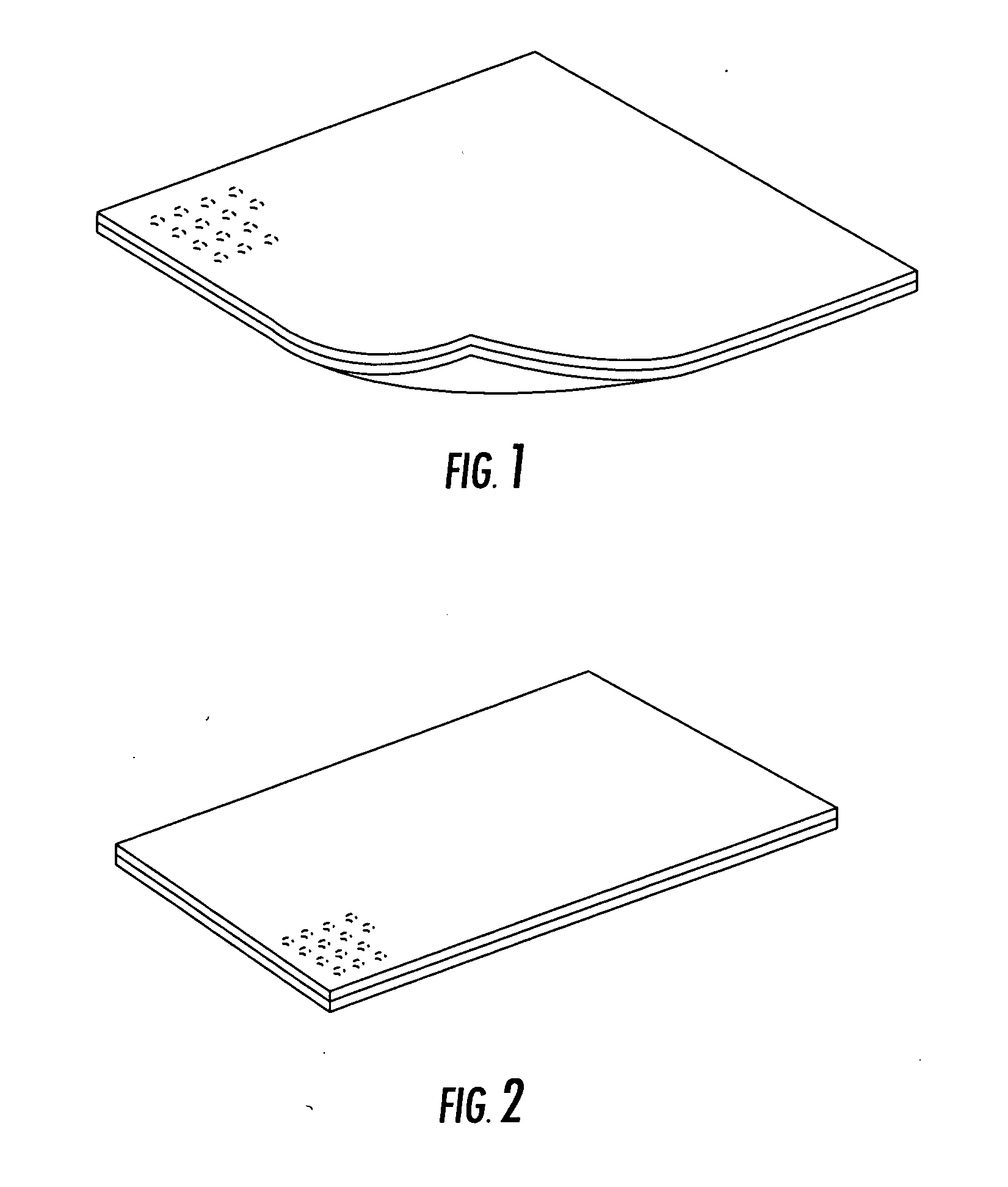

Image

  • Enhancement of barrier fabrics with breathable films and of face masks and filters with novel fluorochemical electret reinforcing treatment
  • Enhancement of barrier fabrics with breathable films and of face masks and filters with novel fluorochemical electret reinforcing treatment
  • Enhancement of barrier fabrics with breathable films and of face masks and filters with novel fluorochemical electret reinforcing treatment

Examples


example a

1) Outer layer of colored SB PP, which may or may not be treated with an alcohol, oil or water repellent finish, which may or may not be electrostatically charged, and which may or may not be treated with an antimicrobial agent.

2) Melt Blown PP behind layer 1 which may or may not be electrostatically charged and may or may not be treated with an antimicrobial agent.

3) Inner layer of cotton-based porous hydroentangled nonwoven worn next to the face, which may also be treated with a chemically bonded antimicrobial compound.

example b

1) Outer layer of colored SB PP which may or may not be electrostatically charged or may or may not be treated with a repellent finish or with an antimicrobial agent.

2) MB PP behind layer 1 in Example B, which may or may not be electrostatically charged and which may or may not be treated with an antimicrobial agent.

3) Inner layer of cotton / PP staple fiber web thermally bonded to a white SB PP (CSN) with the SB PP side adjacent to layer 2 in Example B in which the cotton side is adjacent to the face and may or may not be treated with a non-leachable (non-migrating) antimicrobial agent.

example c

1) Outer layer of colored SB PP which may or may not be treated with an antimicrobial agent.

2) Electrostatically charged MB PP behind layer 1 in Example C.

3) Inner layer of cotton / PP staple fiber web thermally bonded to a SB PP (CSN), in which one or both components may or may not be treated with an antimicrobial agent, and in which the cotton side is adjacent layer 2 in Example C and the SB PP is worn against the face.


PUM

PropertyMeasurementUnit
Thicknessaaaaaaaaaa
Electric chargeaaaaaaaaaa
Pressure dropaaaaaaaaaa

Abstract

A respirable one-ply, two-ply or multi-ply barrier fabric including one web comprising an electrostatically charged melt blown fibers nonwoven or a nanofiber / melt blown fibers nonwoven having a weak cationic emulsifier to reduce surface energy of the fibers so as to minimize penetration and wetting by oily mists and to thereby preserve the effectiveness of electrostatic charges applied to fibers. Also disclosed is a two-layer or multi-ply barrier fabric which has at least one barrier fabric layer which is impermeable to liquids such as water and body fluids, but which allows the transport of moisture vapor through the micropores or by chemical absorption of water through a monolithic membrane, which may have additional barrier layers to include melt blown and nanofiber / melt blown composites. One or more layers of the respirable barrier fabric or the moisture transporting microporous (MP) or monolithic (ML) films or combination thereof may contain an antimicrobial agent, fluorochemical or other protective finish, as well as any of the layers of the respirable filter fabric or any of the layers of the filter ensemble as well as any layer of the liquid barrier moisture transporting barrierfabrics. Furthermore, the protective fabrics may contain a porous or absorbent fabric or film on the body side for enhanced thermal comfort, and other additives may be included in the fabric ensembles such as activated carbon particles, or activated carbon particles, or other sorbents, or superabsorbents o to absorb odors or toxic chemicals.

Description

TECHNICAL FIELD This invention relates to breathable protective garment fabrics and to respirable face mask and respirator laminates which serve as barriers to microbial contaminated aerosols and liquid spills of infectious liquids and which may also decontaminate the dangerous aerosols and liquids. BACKGROUND ART AND DISCLOSURE OF THE INVENTION Nonwoven webs (fabrics) are defined as “sheet” or web structures made by bonding and / or interlocking fibers, yarns or filaments by mechanical, thermal, chemical or solvent means.” These webs do not require the conversion of fibers to yarn. Nonwoven webs are also called bonded or engineered webs and are manufactured by processes other than spinning, weaving or knitting, hence the name “nonwovens.” The basic structure of all nonwovens is a web of fibers or filaments. A single type of fiber or filament may be the basic element of a nonwoven. Fibers that measured in centimeters or inches or fractions thereof are called staple fibers. In genera...

Claims


Application Information

Patent Timeline
IPC IPC(8): A41DA41D13/11A41D31/00A62B7/10A62B23/02A62D5/00A62D9/00B32B5/26D04H1/42D04H1/56D06M15/256D06M15/277D06M16/00
CPCA41D13/1192Y10T428/12972A62B23/025A62D5/00A62D9/00B01D39/1623B01D39/163B01D2239/025B01D2239/0407B01D2239/0435B01D2239/0442B32B5/26D04H1/42D04H1/565D06M15/256D06M15/277D06M16/00A41D31/0083D04H1/56D04H1/407D04H1/425D04H1/4374A41D31/305D04H1/43835D04H1/43838B32B2264/108B32B2571/00B32B3/26
Inventor WADSWORTH, LARRY C.TSAI, PETER PING-YI
Owner TENNESSEE RES FOUND INC UNIV OF
Learn More