High-speed fluidic device
a fluidic device and high-speed technology, applied in the direction of gearing, piston pumps, hoisting equipment, etc., can solve the problems of life as well as in the vibration and noise of gears, the inability to transmit drive power to the impeller, and the problem of life, so as to achieve high transmission efficiency, prevent excessive increase, and reduce the effect of vibration
- Summary
- Abstract
- Description
- Claims
- Application Information
AI Technical Summary
Benefits of technology
Problems solved by technology
Method used
Image
Examples
first embodiment
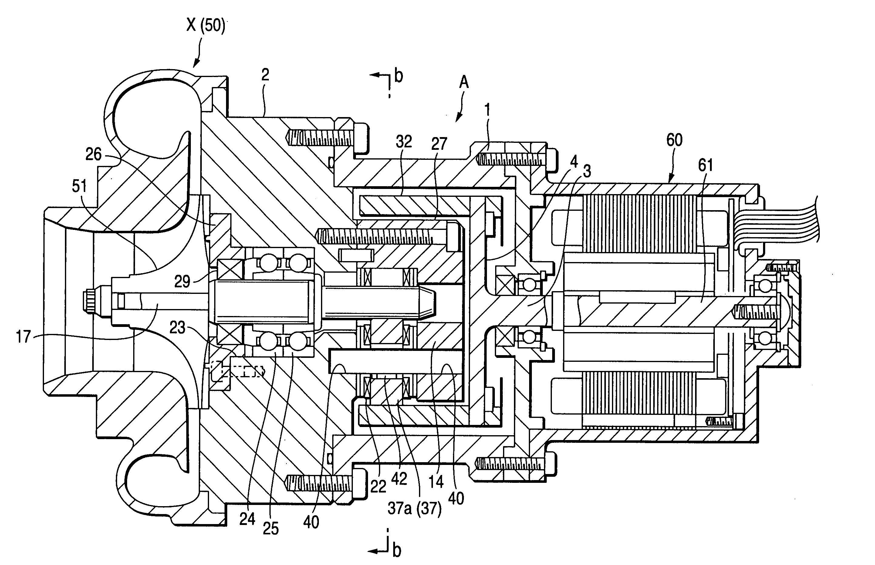
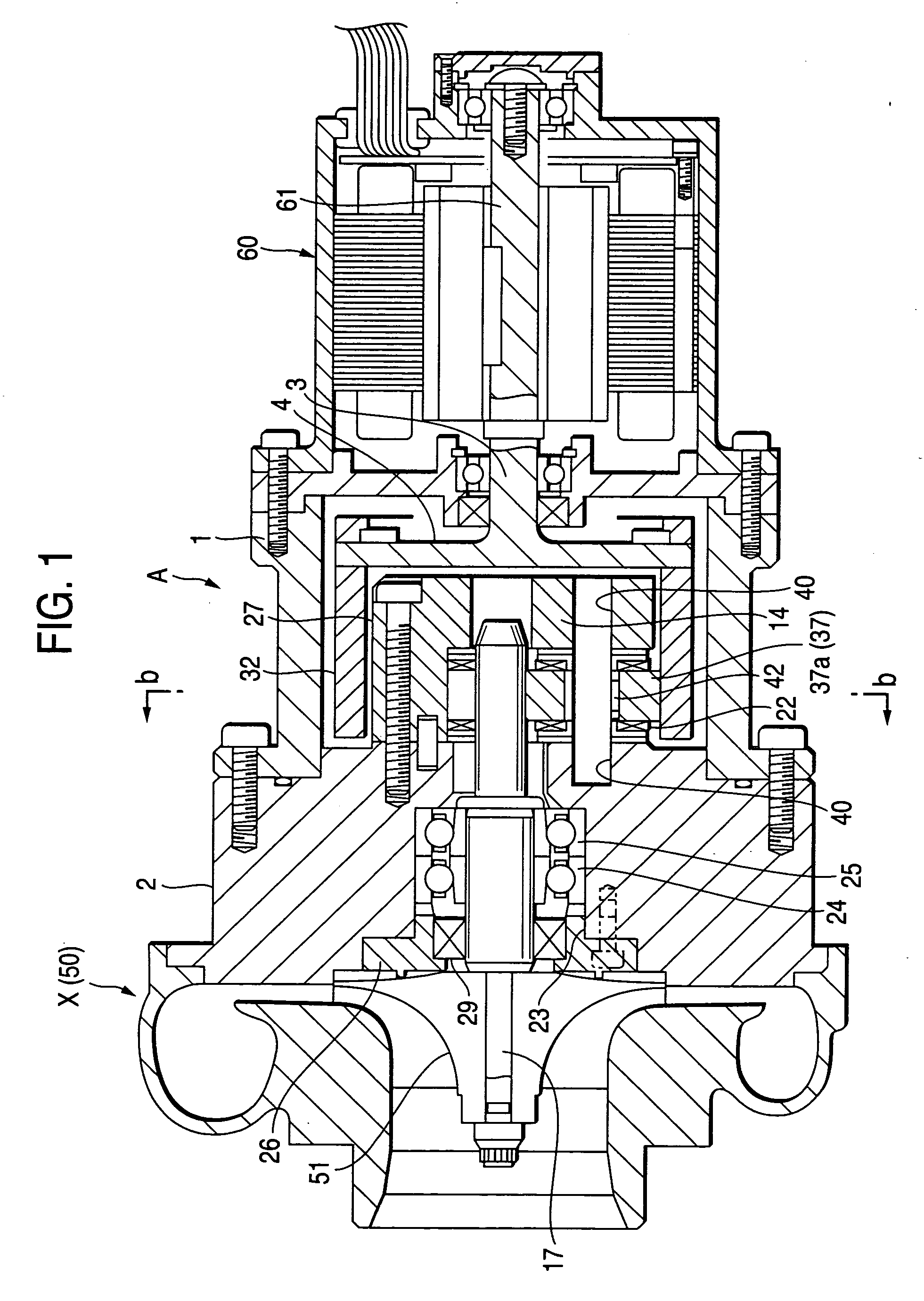
[0095] Further, in this embodiment, the supercharger 50 is used as the high-speed fluidic machine X. The impeller 51 of the supercharger 50 is mounted on an end portion of the high-speed side shaft 17. The drive shaft 61 of the electric motor 60 is integrally connected to the other end portion of the high-speed side shaft 17. The configuration, operation and effect of this embodiment in this case are equivalent to those of the
[0096] Further, this embodiment can be applied not only to the engine supercharger but also to a ventilator for feeding hydrogen as fuel, a blower for blowing out water and water vapor produced by a reaction of hydrogen and oxygen, and so on, for example, in a vehicle powered by fuel battery.
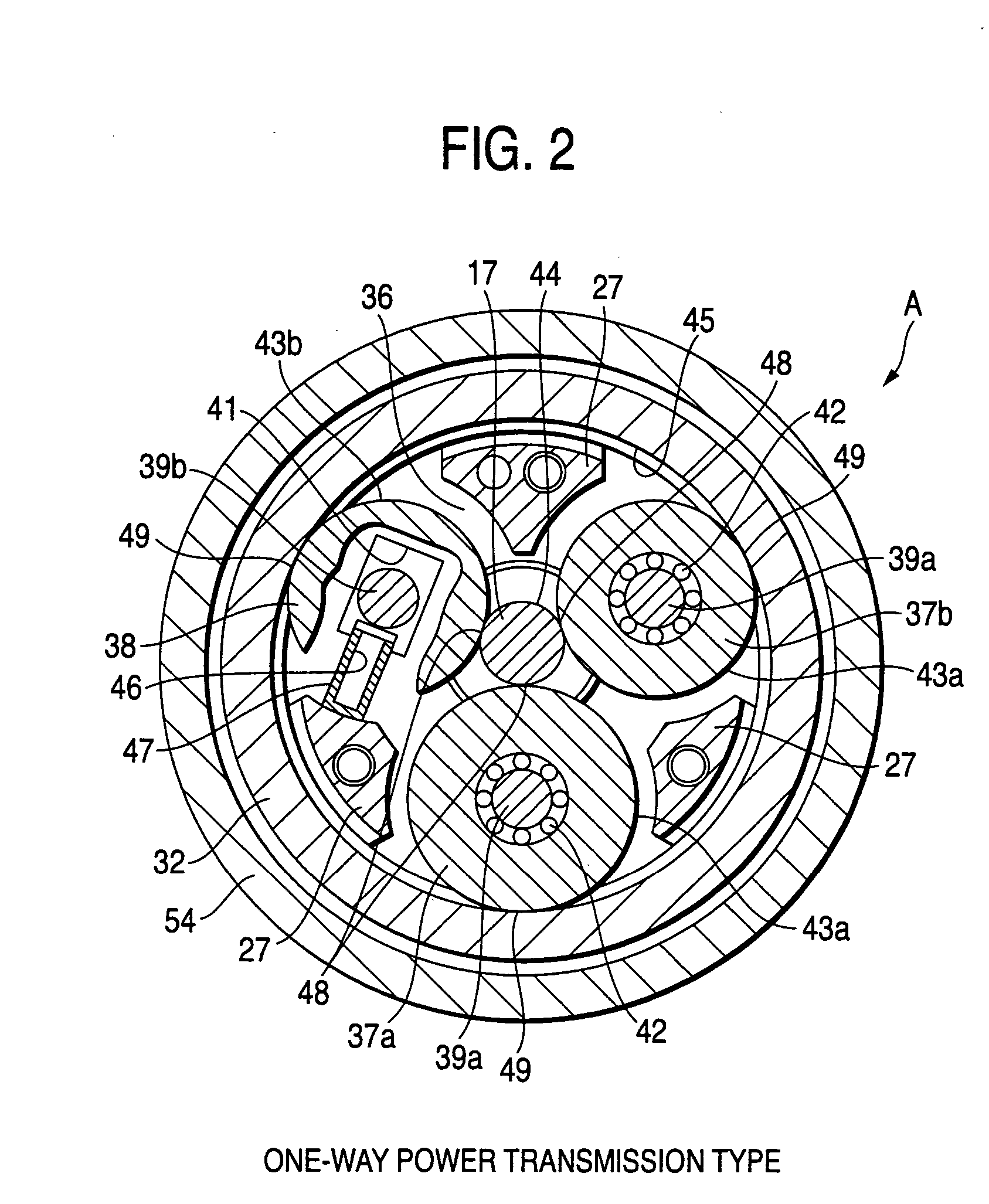
[0097]FIG. 7 is a sectional view of a wedge roller type transmission according to a third embodiment of the invention. A sectional view taken along the line b-b, of the wedge roller type transmission will be omitted because it is equivalent to FIG. 2 or 4. Parts the same a...
sixth embodiment
[0114]FIG. 10 is a vertical sectional view of a high-speed fluidic device according to the invention.
[0115] In this embodiment, as shown in FIG. 10, a supercharger 60 is used as the high-speed fluidic machine X. An impeller 61 of the supercharger 60 is mounted on an end portion of the high-speed side shaft 17. Incidentally, a housing 62 is formed around the impeller 61, an intake port 63 is provided in the axial outside of the impeller 61, and a scroll-shaped supercharging passage 64 is formed in the radial outside of the impeller 61.
[0116] The high-speed side shaft 17 is sealed with a mechanical seal 65 between the impeller 61 and the bearings 56 and 57.
[0117] An electric motor M as a drive source is shaped like a cylinder. The electric motor M includes a cylindrical stator 71 disposed in the housing 1, and a cylindrical rotor 72 rotated by the stator 71.
[0118] Incidentally, the housing 1 is formed so that a cooling water (oil) supply unit 73 can be connected to an upper portion...
seventh embodiment
[0130]FIG. 11 is a vertical sectional view of a high-speed fluidic device according to the invention.
[0131] In this embodiment, as shown in FIG. 11, an oil seal 66 is used as a substitute for the mechanical seal 65.
[0132] That is, the high-speed side shaft 17 is sealed with the oil seal 66 between the impeller 61 and the bearings 56 and 57.
[0133] The other configuration, operation and effect of this embodiment are equivalent to those of the sixth embodiment.
PUM
 Abstract
Description
Claims
Application Information
 - R&D
- Intellectual Property
- Life Sciences
- Materials
- Tech Scout
- Unparalleled Data Quality
- Higher Quality Content
- 60% Fewer Hallucinations
Browse by: Latest US Patents, China's latest patents, Technical Efficacy Thesaurus, Application Domain, Technology Topic, Popular Technical Reports.
© 2025 PatSnap. All rights reserved.Legal|Privacy policy|Modern Slavery Act Transparency Statement|Sitemap|About US| Contact US: help@patsnap.com


