
Safety protocol for industrial controller

Active Publication Date: 2005-03-31
ROCKWELL AUTOMATION TECH
View PDF7 Cites 24 Cited by
  • Summary
  • Abstract
  • Description
  • Claims
  • Application Information

AI Technical Summary

Benefits of technology

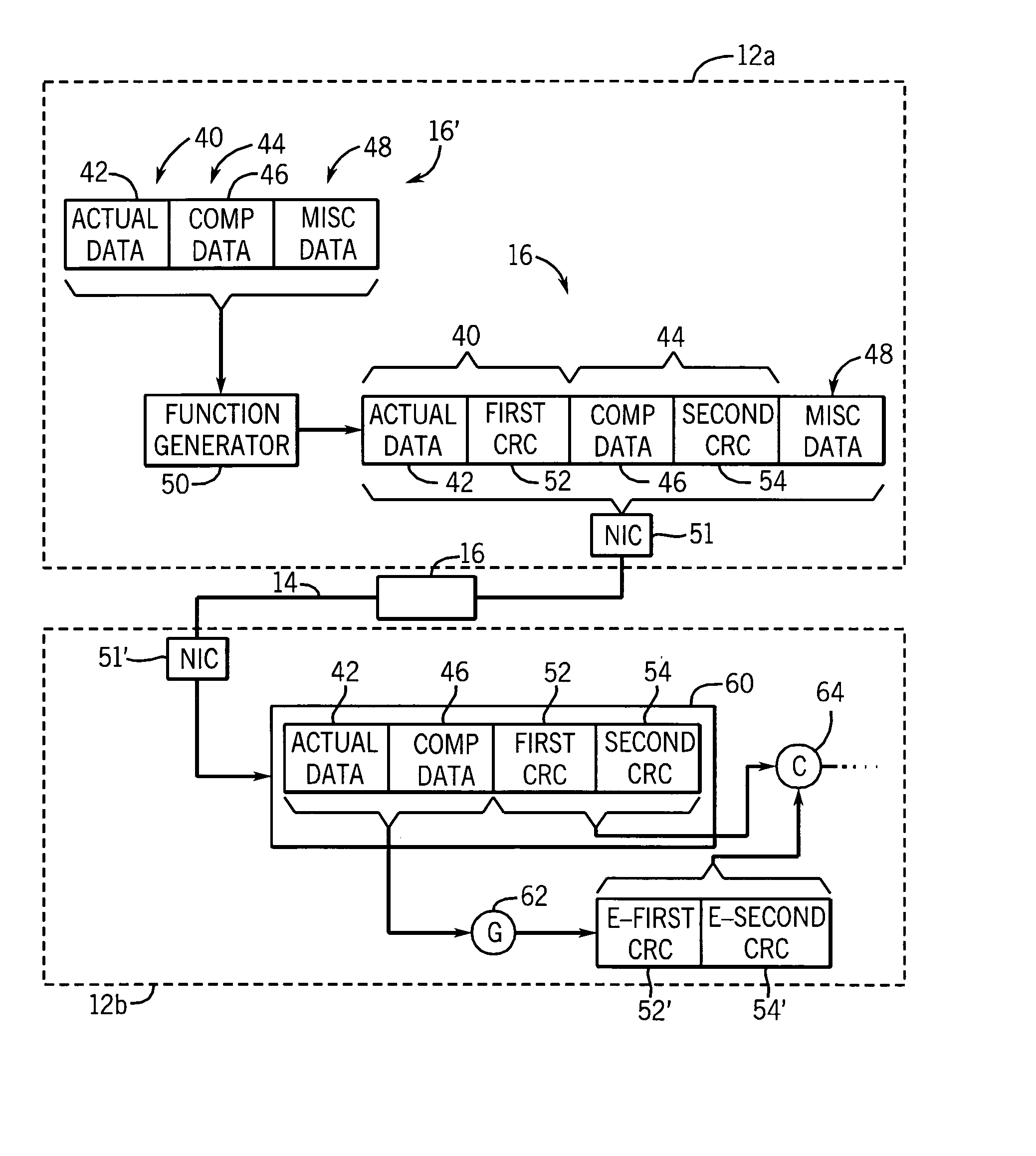
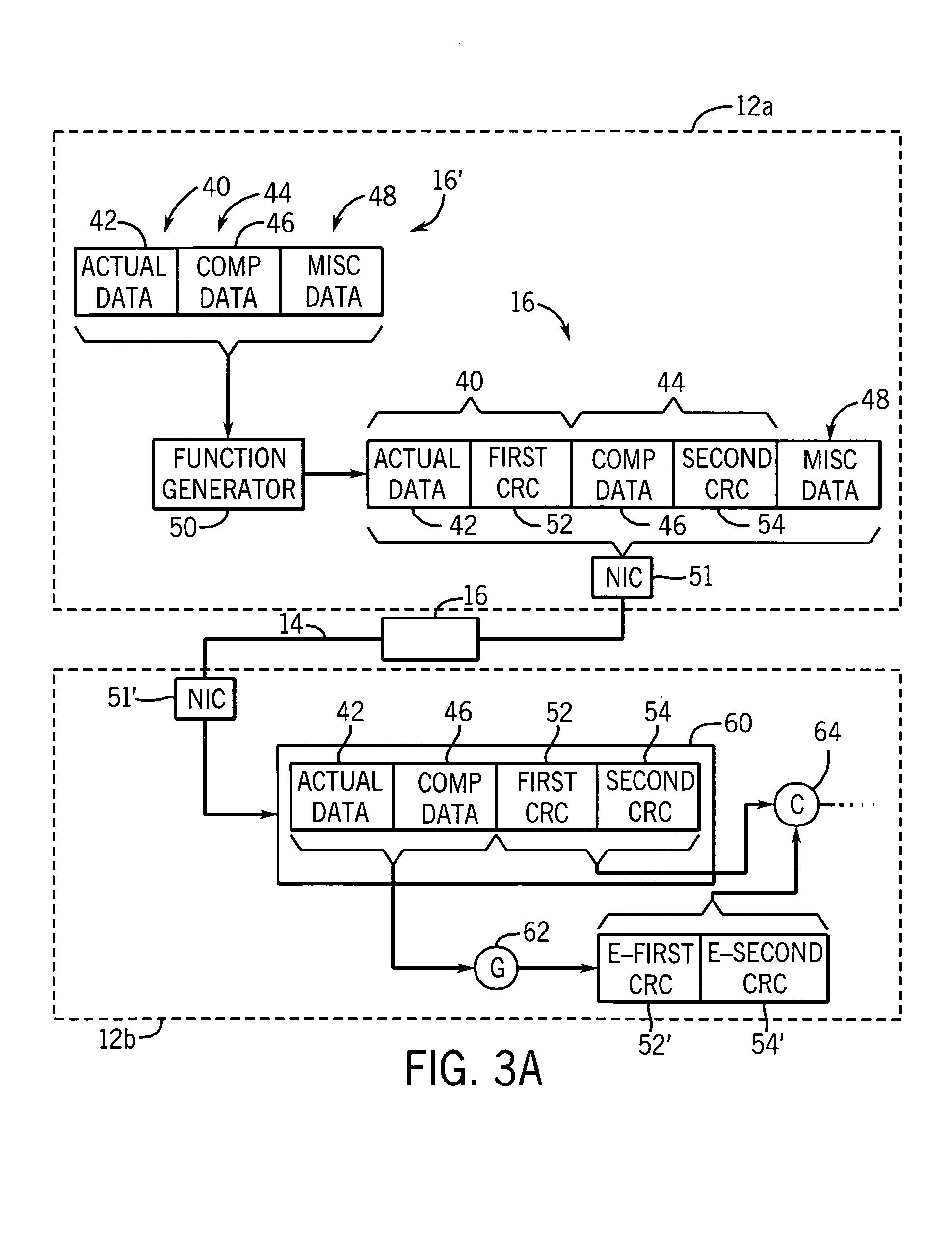
[0011] The present invention provides a network-independent, high-reliability communications system by imposing levels of safety on data that is transmitted over the network while reducing the necessary hardware. The present invention recognizes that safety in data transmission can be achieved with reduced hardware by providing at least one message of data, and providing a compressed representation of the message.

Problems solved by technology

Hard-wired safety systems have proven inadequate as the complexity of industrial processes has increased.
This is in part because of the cost of installing and wiring relays and in part because of the difficulty of troubleshooting and maintaining the “program” implemented by the safety system in which the logic can only be changed by rewiring physical relays and switches.
Unfortunately, conventional high-speed serial communication networks commonly used in industrial control are not sufficiently reliable for safety systems.
For instance, such networks add a large amount of safety information to each message, which increases the message length and thereby reduces the capacity of the network.
This reduced capacity may adversely affect the response time for the industrial controller and / or limit additional reliability enhancing features that might be added to the message to otherwise improve its reliability.
If the amount of safety information embedded in the messages of conventional safety networks is decreased, the reliability of error detection is compromised.

Method used


Image

  • Safety protocol for industrial controller
  • Safety protocol for industrial controller
  • Safety protocol for industrial controller

Examples


Embodiment Construction

[0021] The present invention can be part of a “safety system” used to protect human life and limb in the industrial environment. Nevertheless, the term “safety” as used herein is not a representation that the present invention will make an industrial process safe or that other systems will produce unsafe operation. Safety in an industrial process depends on a wide variety of factors outside of the scope of the present invention including: design of the safety system, installation and maintenance of the components of the safety system, and the cooperation and training of individuals using the safety system. Although the present invention is intended to be highly reliable, all physical systems are susceptible to failure and provision must be made for such failure.

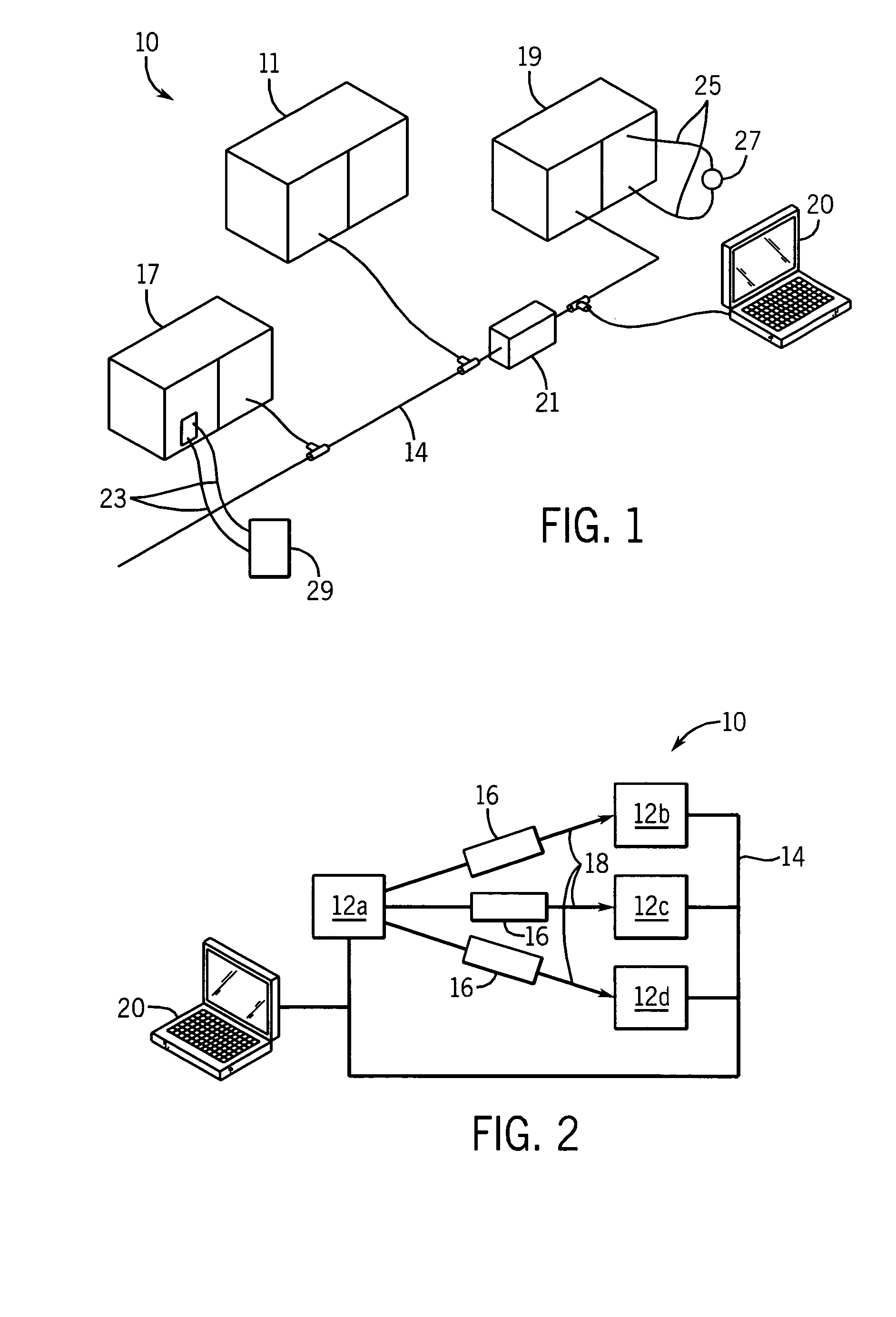
[0022] Referring now to FIG. 1, a high reliability industrial control system 10 for implementing a safety system with the present invention includes a controller 11 communicating on a high speed serial network 14 with remote...


PUM


Abstract

Messages in a high reliability industrial control system are associated with safety messages that enable reliable detection of data errors caused during transmission of the message over the network. In particular, error detection codes are generated and transmitted along with message data. At a receiving node, an expected EDC is generated and compared to the EDC transmitted over the network to determine whether any data was corrupted.

Description

CROSS-REFERENCE TO RELATED APPLICATIONS [0001] Not Applicable. STATEMENT REGARDING FEDERALLY SPONSORED RESEARCH OR DEVELOPMENT [0002] Not Applicable. BACKGROUND OF THE INVENTION [0003] The present invention relates to industrial controllers used for real time control of industrial processes, and in particular, to a high reliability industrial controller appropriate for use in devices intended to protect human health and life. [0004] Industrial controllers are special purpose computers used in controlling industrial processes. Under the direction of a stored control program, an industrial controller examines a series of inputs reflecting the status of the control process and changes a series of outputs controlling the industrial process. The inputs and outputs may be binary, that is, on or off, or analog, providing a value within a continuous range. The inputs may be obtained from sensors attached to the controlled equipment and the outputs may be signals to actuators on the controll...

Claims


Application Information

Patent Timeline
IPC IPC(8): H04L1/00H04L12/00
CPCH04L1/0061H04L2001/0094H04L1/0083H04L1/0065
Inventor GIBART, ANTHONY GERARD
Owner ROCKWELL AUTOMATION TECH
Learn More