
Universal prosthesis with cushioned ankle

a technology of prosthesis and cushioned ankle, which is applied in the field of prosthesis, can solve the problems of limited durability of rubber cushion devices, difficult to provide the level of dynamic response approximating the original ankle and foot, and low-end sach feet that do not provide much energy storage and release, etc., to achieve smooth and natural feeling, improve dynamic response characteristics, and improve wear resistance to the cosmeis

Inactive Publication Date: 2005-03-31
PHILLIPS VAN L +1
View PDF38 Cites 50 Cited by
  • Summary
  • Abstract
  • Description
  • Claims
  • Application Information

AI Technical Summary

Benefits of technology

Accordingly, it is one object and advantage of the present invention to overcome some or all of the above limitations by providing a cushioned ankle prosthetic foot and an associated cosmesis having a slot between the big toe and adjacent toe to allow the amputee to wear thong sandals and the like. The cushioning desirably provides a smooth and more natural-feeling rollover from a heel-strike to a toe-off position and / or improved dynamic response characteristics. Advantageously, the prosthetic foot is configured so that it can be used as either a right or a left foot. Moreover, the cosmesis includes a toe reinforcement strap to desirably provide improved wear resistance to the cosmesis.
to overcome some or all of the above limitations by providing a cushioned ankle prosthetic foot and an associated cosmesis having a slot between the big toe and adjacent toe to allow the amputee to wear thong sandals and the like. The cushioning desirably provides a smooth and more natural-feeling rollover from a heel-strike to a toe-off position and / or improved dynamic response characteristics. Advantageously, the prosthetic foot is configured so that it can be used as either a right or a left foot. Moreover, the cosmesis includes a toe reinforcement strap to desirably provide improved wear resistance to the cosmesis.
In accordance with one preferred embodiment of the invention, a prosthetic foot assembly for a lower limb amputee is provided. The assembly generally comprises a prosthetic foot and an outer cosmesis. The prosthetic foot attaches to a socket or pylon of the lower limb amputee. The prosthetic foot generally comprises a lower foot plate and an upper ankle plate. The lower foot plate includes a symmetric toe configuration and a plurality of slots formed therebetween. The upper ankle plate has a length substantially shorter than the foot plate. The prosthetic foot further comprises an ankle block having a wedged configuration. The ankle block comprises a compressible material and is sandwiched between the foot plate and the ankle plate. The outer cosmesis has a length approximately equal to the length of a natural human foot and has an anterior toe region including a slot substantially aligned with one of the slots of the foot plate. Advantageously, the prosthetic foot assembly permits the lower limb amputee to wear thong sandals and the like and / or provides enhanced performance characteristics.
In accordance with another preferred embodiment of the invention, an outer foot cosmesis is provided. The outer foot cosmesis has a length substantially the same as that of a natural human foot. The cosmesis comprises an inner cavity for receiving a prosthetic foot for attaching to a socket or pylon of a lower limb amputee. The cosmesis has a toe portion comprising at least one slot for receiving a thong of a sandal or other footwear. The cosmesis further comprises a reinforcement patch in the toe portion for improving the wear resistance of the cosmesis.
For purposes of summarizing the invention and the advantages achieved over the prior art, certain objects and advantages of the invention have been described herein above. Of course, it is to be understood that not necessarily all such objects or advantages may be achieved in accordance with any particular embodiment of the invention. Thus, for example, those skilled in the art will recognize that the invention may be embodied or carried out in a manner that achieves or optimizes one advantage or group of advantages as taught herein without necessarily achieving other objects or advantages as may be taught or suggested herein.
All of these embodiments are intended to be within the scope of the invention herein disclosed. These and other embodiments of the present invention will become readily apparent to those skilled in the art from the following detailed description of the preferred embodiments having reference to the attached figures, the invention not being limited to any particular preferred embodiment(s) disclosed.

Problems solved by technology

Specifically, the low end SACH feet do not provide much energy storage and release, as do more sophisticated prosthetic feet.
For such compact prostheses, it is difficult to provide the level of dynamic response approximating the original ankle and foot due to the lack of vertical space available.
Unfortunately, many of these rubber cushion devices have limited durability due to the difficulty in bonding the rubber portions to the solid leg or foot portions, or are relatively complex, requiring several machined parts, which adds to the cost.
Conventional artificial feet and / or cosmesis can disadvantageously also be limited in terms of the flexibility and versatility they provide in allowing the amputee to don different types of conventional footwear.
Moreover, the frictional contact between the artificial foot and the cosmesis can cause wear of the cosmesis, especially at the high stress contact points.
This can not only result in inconvenient frequent replacement of the cosmesis but also further adds to the cost for the amputee.
Additionally, many artificial feet are adapted to be used only as a left or right foot and not both, and this undesirably limits versatility and increases manufacturing and inventory costs.

Method used


Image

  • Universal prosthesis with cushioned ankle
  • Universal prosthesis with cushioned ankle
  • Universal prosthesis with cushioned ankle

Examples


Embodiment Construction

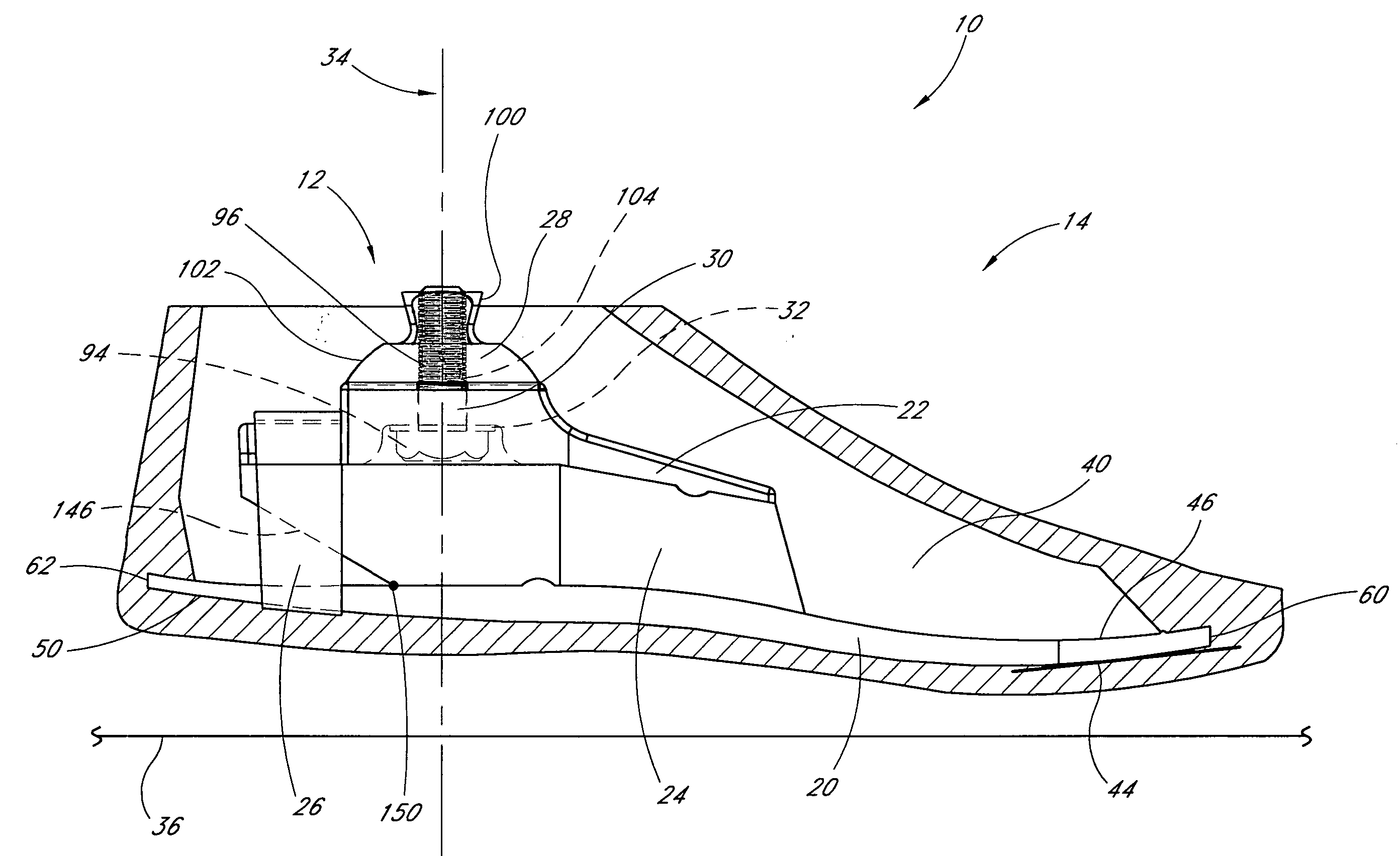
FIGS. 1 and 2 illustrate a prosthetic or artificial foot assembly or combination 10 having features in accordance with one preferred embodiment of the present invention. The prosthetic foot assembly or foot prosthesis 10 generally comprises a prosthetic or artificial foot 12 and an outer foot cover or cosmesis 14. For clarity, a sectional illustration of the cosmesis 14 is shown in FIGS. 1 and 2. FIG. 3 is a rear view of the prosthetic foot 12.

The prosthetic foot or prosthesis 12 generally comprises a lower foot plate 20, an upper, smaller ankle plate 22, and a layer or block 24 of resilient material sandwiched between and connecting the foot plate 20 to the ankle plate 22. In one preferred embodiment, the lower foot plate 20 comprises a symmetric toe configuration, thereby desirably permitting the prosthetic foot 12 to be used as either a left or right foot. Advantageously, this saves on manufacturing and inventory costs.

Preferably, and as discussed in greater detail below, the ...


PUM


Abstract

The invention provides a cushioned ankle prosthetic foot and a cosmesis having a slot between the big toe and adjacent toe to allow the amputee to wear thong sandals and the like. The cushioning desirably provides a smooth and more natural-feeling rollover from a heel-strike to a toe-off position and / or improved dynamic response characteristics. Advantageously, the prosthetic foot is configured so that it can be used as either a right or a left foot. Moreover, the cosmesis includes a toe reinforcement strap to desirably provide improved wear resistance to the cosmesis.

Description

BACKGROUND OF THE INVENTION 1. Field of the Invention The present invention relates generally to prosthetic feet and, more particularly, to a prosthetic foot having a cushioned ankle and a thong-receiving reinforced outer foot cosmesis. 2. Description of the Related Art In the prosthetics market, the conventional SACH foot has been the most widely prescribed artificial foot over the past several decades. The SACH foot generally includes a solid ankle and cushioned heel foot mounted to a limb along an approximate hinge axis taken through the ankle. The SACH foot has been popular precisely for its simplicity, and thus economy, but includes certain drawbacks in terms of dynamic response characteristics. Specifically, the low end SACH feet do not provide much energy storage and release, as do more sophisticated prosthetic feet. Some patients undergo what is known in the art as a Symes amputation, where the foot is severed from the leg near the ankle region. Because the Symes patien...

Claims


Application Information

Patent Timeline
Patent Type & Authority Applications(United States)
IPC IPC(8): A61F2/00A61F2/50A61F2/66A61F2/76A61F2/78
CPCA61F2/66A61F2/76A61F2002/30434A61F2002/30464A61F2002/5001A61F2002/5007A61F2220/0075A61F2002/6628A61F2002/665A61F2002/6685A61F2002/7862A61F2220/0041A61F2002/6621A61F2002/30433A61F2002/30462
Inventor PHILLIPS, VAN L.POUCHAK, HILARY D.
Owner PHILLIPS VAN L
Learn More