
Infrared radiator embodied as a surface radiator

a technology of infrared radiator and surface, which is applied in the direction of burners, combustion types, burner material specifications, etc., can solve the problem of insufficient heat transfer and achieve the effect of improving heat transfer and high service li

Inactive Publication Date: 2005-03-31
VOITH PATENT GMBH
View PDF9 Cites 6 Cited by
  • Summary
  • Abstract
  • Description
  • Claims
  • Application Information

AI Technical Summary

Benefits of technology

The present invention provides an infrared radiator with improved heat transfer and high service life. It includes a combustion chamber with a gas-permeable barrier and a radiant element with ducts that emit infrared radiation. A jet plate with individual jets and the ducts of the radiant element are closed on the combustion chamber side, at least in the region of the outlet openings of the jets, by which baffle surfaces are formed, and toward which the outlet openings of the jets are aimed. The jets have a high outlet velocity, which is essential for efficient, convective heat transfer. The baffle surfaces prevent the flame from forming within the radiant element, ensuring maximum, effective heat transfer. The invention has various refinements that are preferred for further improvement.

Problems solved by technology

Because of the high velocity, the baffle surfaces prevent the flame only forming within the radiant element, and thus no sufficient heat transfer taking place at the latter.

Method used


Image

  • Infrared radiator embodied as a surface radiator
  • Infrared radiator embodied as a surface radiator
  • Infrared radiator embodied as a surface radiator

Examples


Embodiment Construction

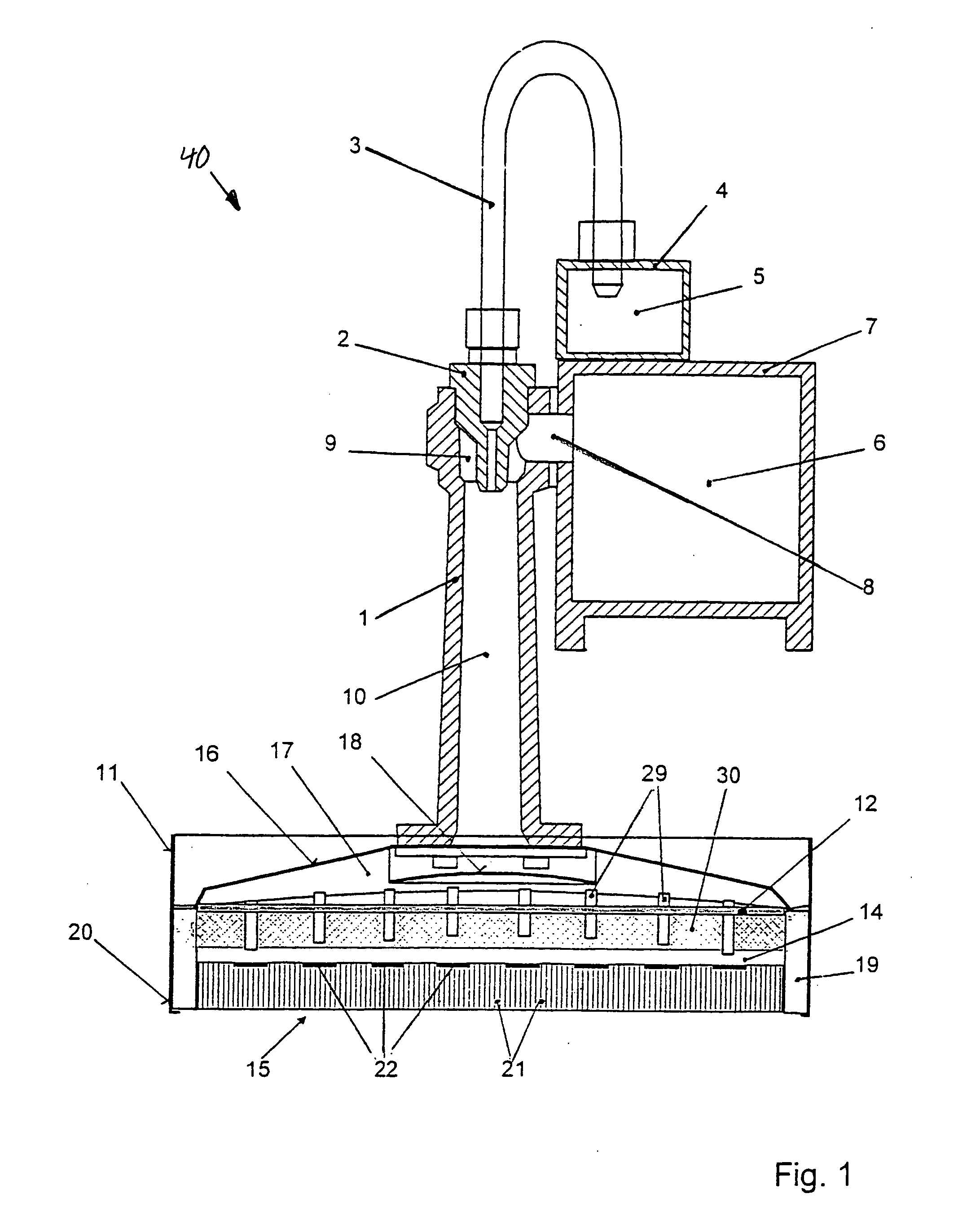
[0027] Referring now to the drawings, and more particularly to FIG. 1, each radiator 40 contains a mixing pipe 1, into which a mixing jet 2 is screwed at one end. Connected to mixing jet 2 is a gas supply line 3, which is connected to a manifold line 4, from which a plurality of radiators arranged beside one another are supplied with gas 5. The supply with air 6 is provided via a hollow cross member 7, to which mixing pipe 1 is fixed. A connecting line 8 for the air supply opens in the upper part of mixing pipe 1 into an air chamber 9 which is open at the bottom and surrounds the outlet end of mixing jet 2, so that a gas-air mixture is introduced into mixing chamber 10 of mixing pipe 1 from above.

[0028] The infrared radiators according to the present invention are preferably heated with gas; alternatively, heating with a liquid fuel as a heating fluid is possible.

[0029] Fixed at the lower, open end of mixing pipe 1 is a housing 11, in which a jet plate 12 is arranged as a barrier....


PUM


Abstract

A combustion chamber which is bounded on one side by a gas-permeable barrier, on the other side by a radiant element. The radiant element having a large number of ducts and emitting infrared radiation at its front surface. A jet plate with individual jets and the ducts of the radiant element are closed on the combustion chamber side, at least in the region of the outlet openings of the jets, by which baffle surfaces are formed, and toward which the outlet openings of the jets are aimed.

Description

CROSS REFERENCE TO RELATED APPLICATIONS [0001] This is a continuation of PCT application No. PCT / DE03 / 00401, entitled “INFRARED RADIATOR EMBODIED AS A SURFACE RADIATOR”, filed Feb. 11, 2003. BACKGROUND OF THE INVENTION [0002] 1. Field of the Invention [0003] The present invention relates to an infrared radiator, and more particularly, an infrared radiator embodied as a surface radiator. [0004] 2. Description of the Related Art [0005] Infrared radiators embodied as surface radiators are used in dryer systems which are used to dry web materials, for example, paper or board webs. Depending on the width of the web to be dried and the desired heating output, the requisite number of radiators is assembled with aligned emission surfaces to form a drying unit. [0006] The basic structure of a single generic infrared radiator is illustrated in FIG. 8 and described, for example, in DE 199 01 145-A1. [0007] The fuel / air mixture needed for the operation of the radiator is supplied to the radiato...

Claims


Application Information

Patent Timeline
Patent Type & Authority Applications(United States)
IPC IPC(8): F23D14/14
CPCF23D14/14F23D2900/14123F23D2212/10F23D2203/102F23D14/147F23D14/145
Inventor AUST, RICHARDPANIAGUA, JUAN
Owner VOITH PATENT GMBH
Learn More