Method and device for production of radio-isotopes from a target

Inactive Publication Date: 2005-03-31
ION BEAM APPL
View PDF3 Cites 23 Cited by
  • Summary
  • Abstract
  • Description
  • Claims
  • Application Information

AI Technical Summary

Benefits of technology

Preferably, the use of a tubular heater or oven is very convenient. This is due to the fact that the heating profile of said device is very homogeneous. Furthermore, the control of the t

Problems solved by technology

In addition, such separation techniques are complex to implement and effluents are generated that may prove to be hazardous and polluting.
In particular, the acidic solutions used for the separation will be contaminated with radioactive waste and will require decontamination, which substantially increases the cost of the process.
Finally, unfortunately, this separation process totally destroys the target, and hence rhodium, which is a particularly expensive material.
Consequently, the target cannot be reused for a further irradiation.
The addition of said metallic reagent will also destroy the crystalline structure of the target.

Method used


Image

  • Method and device for production of radio-isotopes from a target
  • Method and device for production of radio-isotopes from a target
  • Method and device for production of radio-isotopes from a target

Examples


first embodiment

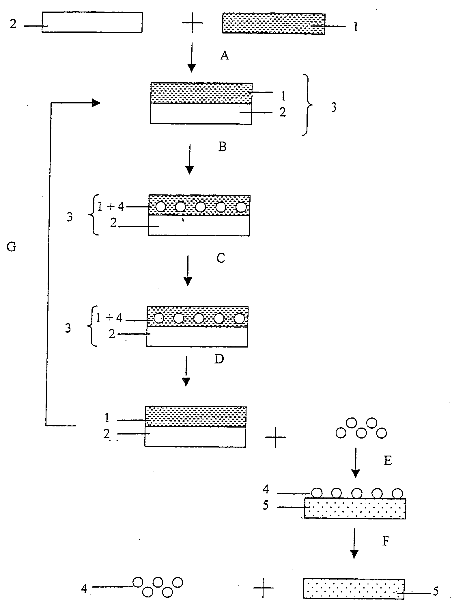
FIG. 1a diagrammatically describes the various steps of the process for producing a radioisotope according to the present invention.

Reference is made to the preparation of the radioisotope 103Pd, referenced 4, from a target 3 comprising rhodium 103Rh, the isotope precursor, referenced 1, by irradiation with a proton beam.

At the start, it is first a matter of preparing the target 3 comprising the precursor 1 of the radioisotope 4 (step A—preparation of the target). To do this, a deposit of Rh is placed on a metal plate 2, which is, in the present case, a copper plate. This is usually performed by electrolysis, so as to obtain a deposit whose thickness is such that the proton beam used during the irradiation (for example a 14 MeV proton beam) loses at least three quarters of its energy in the target. However, other deposition techniques, for instance evaporation, and plasma deposition techniques (direct current (DC), radiofrequency or microwaves) in vacuum or atmospheric plasma (pl...

second embodiment

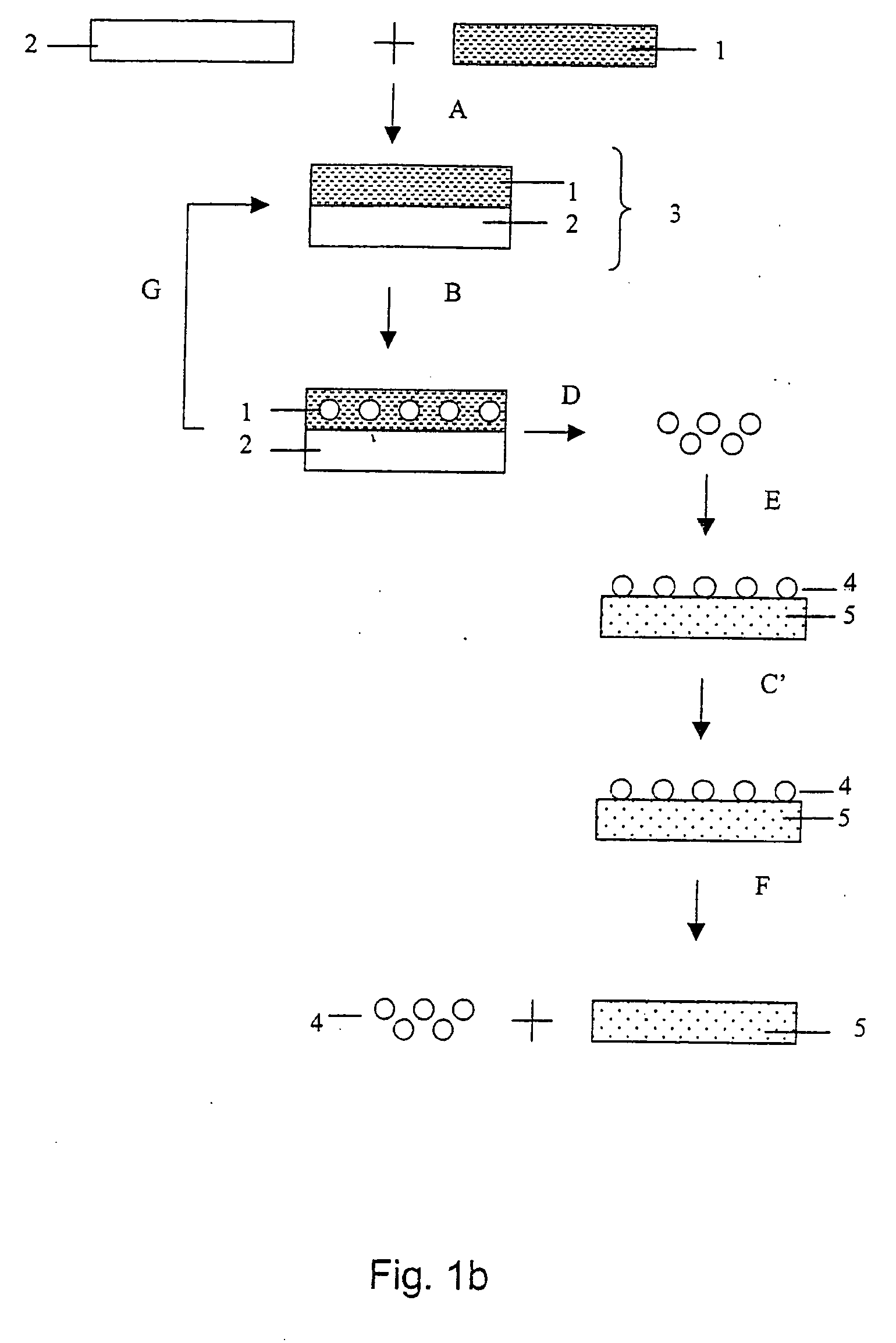
FIG. 1b diagrammatically describes the various steps of the process for producing a radioisotope according to the present invention, in which the effusion step is performed on-line, i.e. directly in the irradiation chamber.

The making of the target (step A) is performed in the same manner as in the first embodiment. As shown in FIG. 3, a collection substrate 5 is installed in the irradiation chamber. It is therefore not necessary to extract target 3 in order to proceed to the effusion-collection. This device allows the irradiation and the effusion-collection to be performed simultaneously (simultaneous steps B, D and E). The energy required to heat the target is totally or partially provided by the accelerated particle beam. After irradiation, the collection substrate 5 is extracted from the irradiation chamber 10. The separation of the deposited palladium (step F) is then performed in the same manner as in the first embodiment. Target 3 can remain in the irradiation chamber 10.

FIG...


PUM


Abstract

The invention relates to a method for production of a radio-isotope (4) from a target (3), containing a precursor (1) of said radio-isotope (4), using a beam of accelerated particles, comprising the following method steps: preparation of a target (3), containing the precursor (1) of the radioisotope (4), irradiation of said target (3) within an irradiation chamber (10) with a beam of accelerated particles in order to induce the transmutation of the precursor (1) into the radio-isotope (4), heating said target (3) in order to bring about the efflux of the radio-isotope (4) from the target (3), collection of said radio-isotope (4), extracted as a gas and condensation of said radio-isotope (4) into a solid or liquid. The invention further relates to a device for carrying out the above method and use of the device and method for the production of palladium 103 from rhodium 103.

Description

SUBJECT OF THE INVENTION The present invention relates to a process and a device for producing radioisotopes from a target consisting essentially of an isotope precursor that is irradiated with an accelerated particle beam, the radioisotope being separated from its precursor once it has been produced. One particular application of the present invention relates to the production of palladium-103 from rhodium-103. PRIOR ART Radioisotopes are usually produced by bombarding or irradiating a target consisting essentially of an isotope precursor using an accelerated particle beam. A nuclear reaction is produced therein, which causes a fraction of the isotope precursor present to be converted into a radioisotope. It should be noted that, in most cases, the radioisotope created is intimately mixed with the isotope precursor material constituting the target and consequently remains in said target. Thereby, only a small percentage of the precursor is usually converted into usable radiois...

Claims


Application Information

Patent Timeline
IPC IPC(8): G21G1/10
CPCG21G1/10
Inventor BRICAULT, RAYLUCAS, STEPHANE
Owner ION BEAM APPL
Why Eureka
Try Eureka