
Control apparatus for an electrically driven power steering

a control apparatus and power steering technology, applied in the direction of electric devices, brake systems, tractors, etc., can solve the problems of excessive current protection, sudden change of the driving position, short restoration time of the motor current, etc., to reduce the cost, suppress the heat generated by the motor, and the effect of not worsening the steering feeling

Active Publication Date: 2005-03-31
DENSO CORP
View PDF5 Cites 12 Cited by
  • Summary
  • Abstract
  • Description
  • Claims
  • Application Information

AI Technical Summary

Benefits of technology

[0010] In view of the above-described problems, the present invention has an object to provide an electrically driven power steering apparatus that is capable of protecting a motor and its peripheral circuit against excessive current without worsening the steering feeling due to reduction in the steering assist force during such a current protecting operation.
[0011] In order to accomplish the above and other related objects, the present invention provides an electrically driven power steering control apparatus for a vehicle that gives a steering assist torque to a steering mechanism by supplying electric power to an electrically driven motor based on a steering operation made by a driver, including tiredness detecting means and driving control means. The tiredness detecting means detects the tiredness (or fatigue) of a driver. The driving control means restricts an operation of the electrically driven motor based on the tiredness detected by the tiredness detecting means. According to this arrangement, the driving control means restricts the operation of the electrically driven motor based on the detected tiredness of a driver. Thus, the present invention can protect a motor and its peripheral circuit against excessive current without worsening the steering feeling due to reduction in the steering assist force during such a current protecting operation.
[0012] According to a preferred embodiment of the present invention, the electrically driven power steering control apparatus can drive the electrically driven motor based on a traveling speed of the vehicle and a steering force caused by a steering operation made by a driver. According to this arrangement, the electrically driven motor can be controlled in accordance with driving conditions of a vehicle. Thus, it becomes possible to prevent the steering feeling from being worsened.

Problems solved by technology

According to the above-described conventional electrically driven power steering apparatus, a motor burnout preventing mechanism starts its operation when a driver must manage to put a vehicle into a garage or into a limited parking space by repetitively turning a steering wheel for a relatively long time.
Such an abrupt increase in the steering torque will force a driver to feel sudden change in the reaction force returning from the steering wheel or feel abnormal behavior in the steering wheel.
A restoration time of the motor current becomes short.
In general, an excessive current protection decreases a steering assist force.
However, this apparatus prevents the steering feeling from being worsened due to such reduction in the steering assist force (refer to Japanese Patent Application Laid-open No. 2002-78379).
Accordingly, it was difficult to completely eliminate strange feeling during a steering operation made by a driver.
In other words, it is difficult to use a common control program for numerous types of electrically driven power steering apparatuses.
The costs required in the research and development stage will increase.
Thus, the costs required in the research and development stage will increase.

Method used


Image

  • Control apparatus for an electrically driven power steering
  • Control apparatus for an electrically driven power steering
  • Control apparatus for an electrically driven power steering

Examples


first embodiment

[0039] Hereinafter, an electrically driven power steering control apparatus in accordance with a first embodiment of the present invention will be explained with reference to attached drawings.

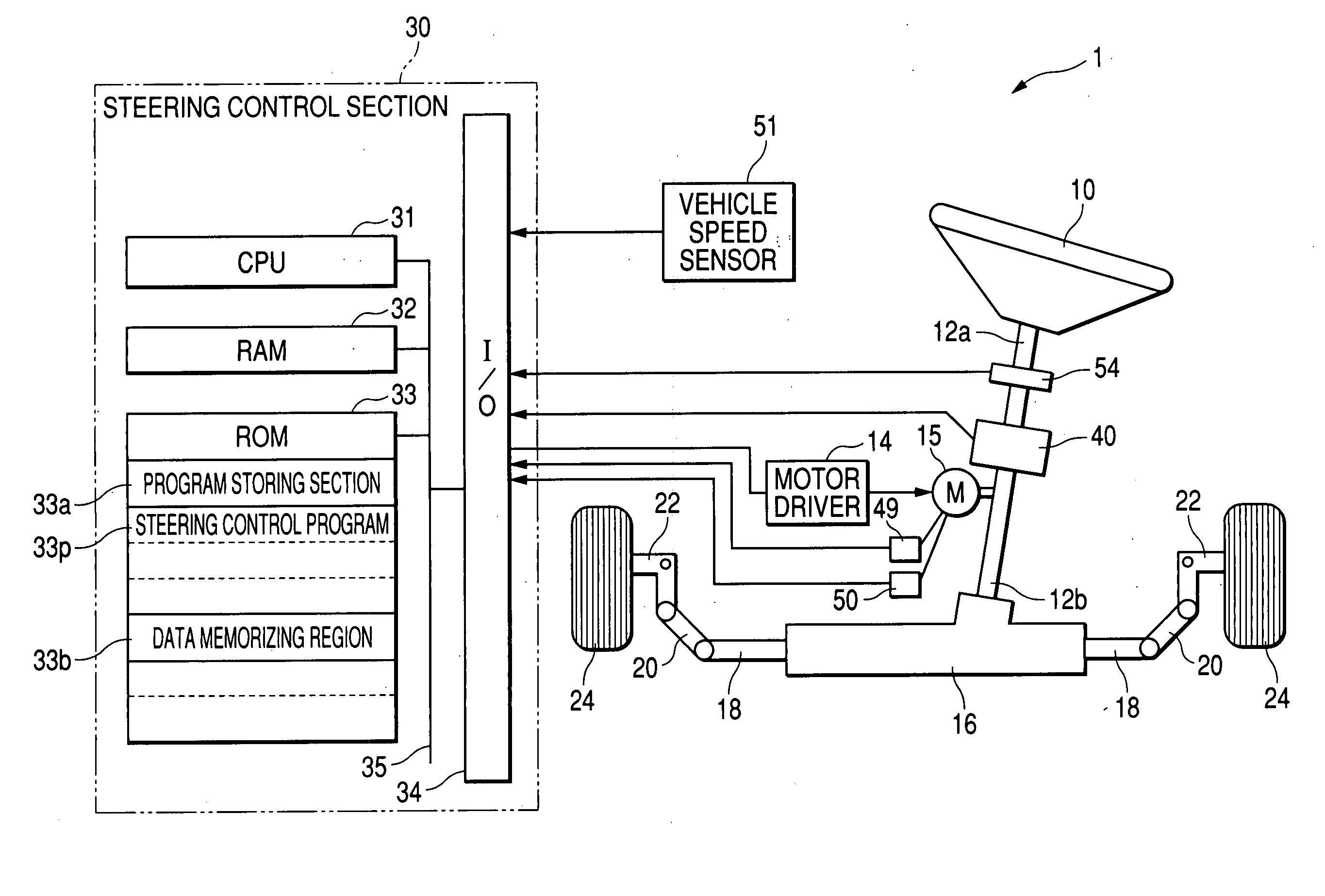
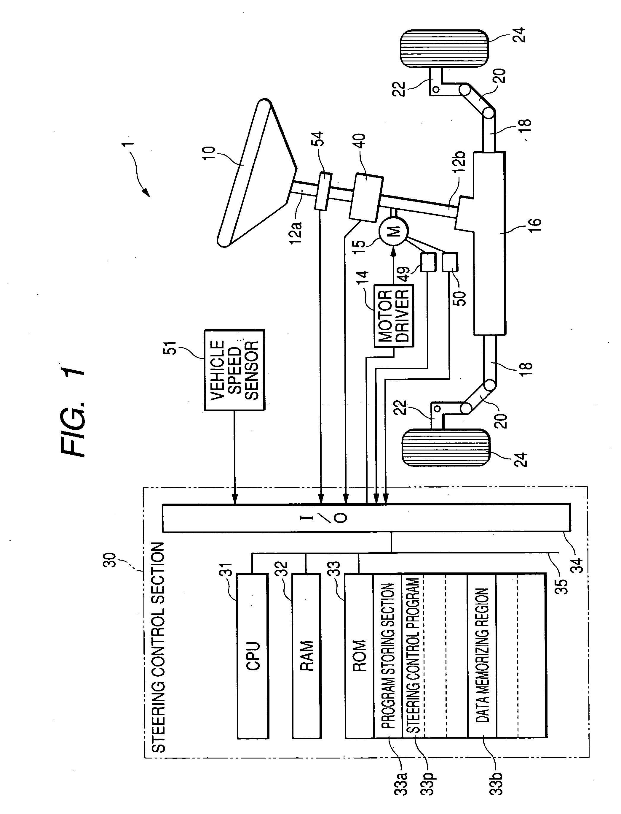
[0040]FIG. 1 is a schematic block diagram showing an overall arrangement of an electrically driven power steering control apparatus 1.

[0041] A steering wheel 10 is fixed to an upper end of a steering shaft 12a. The steering shaft 12a has a lower end connected to a steering torque detecting section 40. An upper end of a pinion shaft 12b is connected to the steering torque detecting section 40. Furthermore, a pinion (not shown) is provided at a lower end of the pinion shaft 12b. This pinion meshes or engages with a rack bar 18 disposed in a steering gearbox 16. Furthermore, each end of the rack bar 18 is connected to an inner end of a corresponding tie rod 20. The outer end of each tie rod 20 is connected to a steerable wheel 24 via knuckle arm 22. An assist motor 15 is attached to the pinion ...

second embodiment

[0058] Hereinafter, an electrically driven power steering control apparatus in accordance with a second embodiment of the present invention will be explained with reference to attached drawing. The electrically driven power steering apparatus according to the second embodiment is structurally identical with the electrically driven power steering apparatus in accordance with the first embodiment of the present invention shown in FIG. 1. Accordingly, the second embodiment will be explained by using the same reference numerals attached to various components of the first embodiment of the present invention shown in FIG. 1.

[0059] A steering angle detecting section 54 detecting a steering angle of the steering wheel 10 is attached to the steering shaft 12a of the electrically driven power steering control apparatus 1 shown in FIG. 1. The steering angle detecting section 54 is constituted by a conventionally known angle detecting device, such as a rotary encoder or an angular resolver.

[0...


PUM


Abstract

An electrically driven power steering control apparatus for a vehicle gives a steering assist torque to a steering mechanism by supplying electric power to an electrically driven motor based on a steering operation made by a driver. This control apparatus detects tiredness of a driver, and restricts an operation of the electrically driven motor based on the detected tiredness of a driver.

Description

BACKGROUND OF THE INVENTION [0001] The present invention relates to an electrically driven power steering control apparatus, and more specifically relates to a protecting apparatus that is capable of restricting a current flowing in a motor to prevent the motor and its control circuit from being excessively heated, thereby protecting the motor and its control circuit against heat deterioration or thermal failure. [0002] An electrically driven power steering apparatus includes a motor that generates a steering assist torque to be added to a steering mechanism. To avoid the burnout of a motor, the magnitude of drive current supplied to a motor should be restricted. For example, there is a method for restricting a drive current supplied to a motor to suppress excessive heating or burnout of the motor. In this case, a current restricting operation begins when a predetermined time has passed after starting the steering operation, and then the motor drive current decreases along a predete...

Claims


Application Information

Patent Timeline
Patent Type & Authority Applications(United States)
IPC IPC(8): B62D5/04B62D6/00B62D101/00B62D113/00B62D119/00
CPCB62D6/007B62D5/0463
Inventor HAYASHI, JIROU
Owner DENSO CORP
Learn More