
System and method for statistical timing analysis of digital circuits

a technology of digital circuits and statistical timing analysis, applied in the field of system and method of statistical static timing analysis of digital circuits, can solve the problems of linear complexity of timing analysis in the size of the graph and the number of sources

Active Publication Date: 2005-03-24
GLOBALFOUNDRIES US INC
View PDF0 Cites 68 Cited by
  • Summary
  • Abstract
  • Description
  • Claims
  • Application Information

AI Technical Summary

Problems solved by technology

The timing analysis complexity is linear in the size of the graph and the number of sources of variation.

Method used


Image

  • System and method for statistical timing analysis of digital circuits
  • System and method for statistical timing analysis of digital circuits
  • System and method for statistical timing analysis of digital circuits

Examples


Embodiment Construction

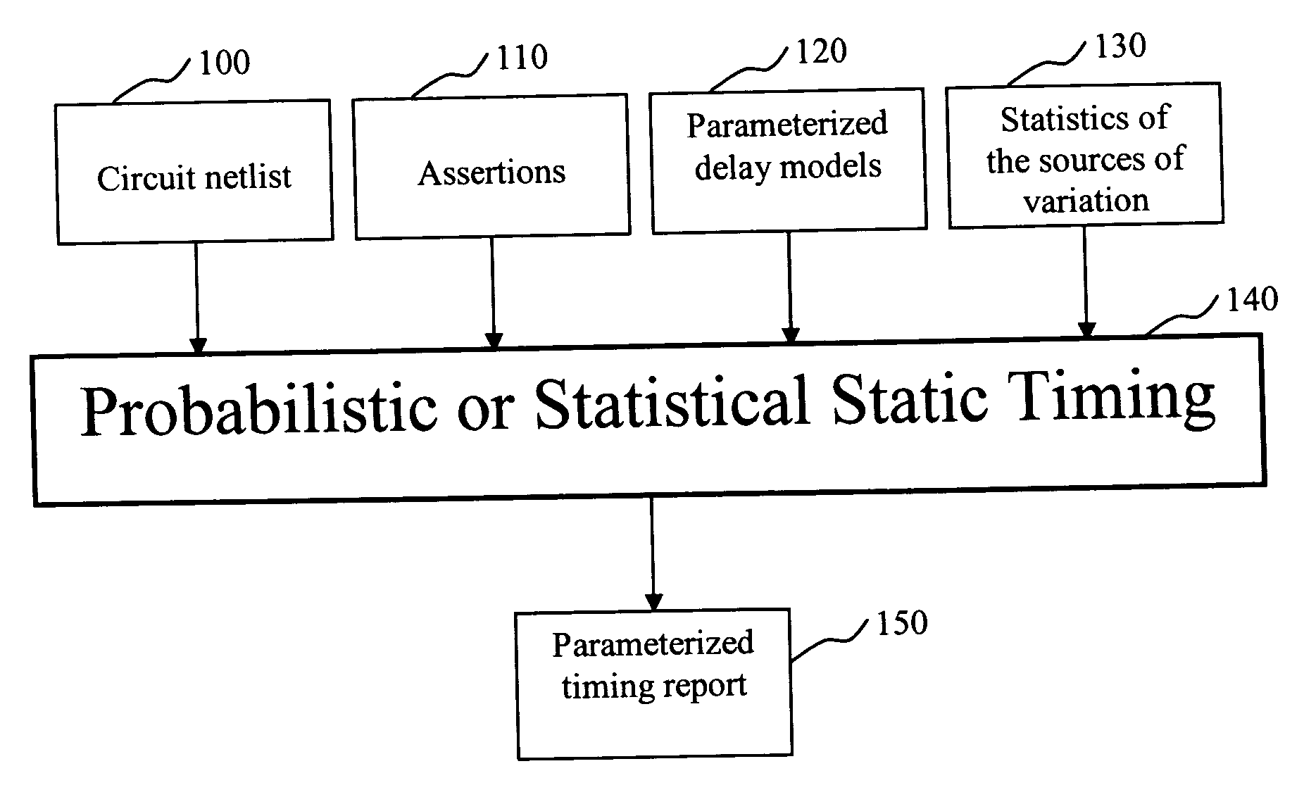
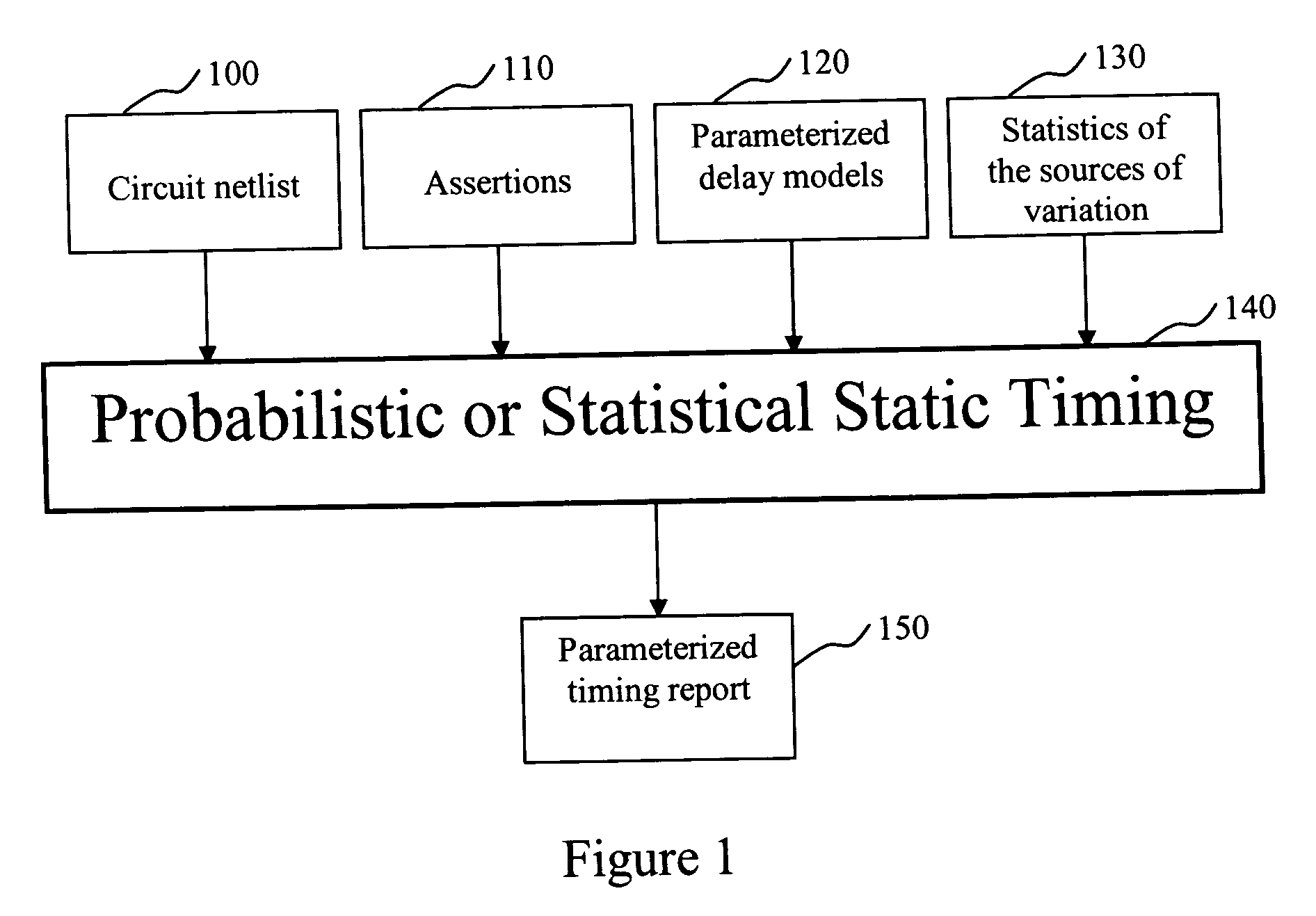
An inventive statistical or probabilistic static timing flow is shown in FIG. 1. The first input is the netlist representing the structure of the circuit to be analyzed, shown in box 100. The second input is a set of timing assertions, box 110. These typically include arrival times at the primary inputs, required arrival times at the primary outputs, information about the phases of the clock, and details of external loads that are driven by the primary outputs. The assertions can be in the form of deterministic numbers or independent probability distributions or correlated probability distributions. The third input is a set of parameterized delay models, box 120. These allow the timer to determine the delay of a gate or wire as a function not only of traditional delay-model variables (like input slew or rise / fall time, and output load) but also as a function of the sources of variation. For example, a first-order linear model may be employed, like the one shown below: delay=a0+∑i=...


PUM


Abstract

The present invention is a system and method for statistical or probabilistic static timing analysis of digital circuits, taking into account statistical delay variations. The delay of each gate or wire is assumed to consist of a nominal portion, a correlated random portion that is parameterized by each of the sources of variation and an independent random portion. Arrival times and required arrival times are propagated as parameterized random variables while taking correlations into account. Both early mode and late mode timing are included; both combinational and sequential circuits are handled; static CMOS as well as dynamic logic families are accommodated. The timing analysis complexity is linear in the size of the graph and the number of sources of variation. The result is a timing report in which all timing quantities such as arrival times and slacks are reported as probability distributions in a parameterized form.

Description

FIELD OF THE INVENTION This invention relates to design automation of digital integrated circuits. More specifically, it relates to static timing analysis of digital circuits in the presence of delay variations. Yet more specifically, the invention relates to propagating arrival and required arrival times of a digital circuit in a probabilistic or statistical fashion, while considering and preserving correlations between the delays of various circuit elements. BACKGROUND OF THE INVENTION With each succeeding generation of integrated circuit technology, variability is proportionately increasing. The sources of such variability include manufacturing variations, device fatigue, environmental variations and phase-locked loop (PLL) variations. In the case of manufacturing variations, the front-end-of-the-line (FEOL) which are the layers that define the active transistors show variation in the transistor's electrical characteristics. Physical quantities such as the length of the gate, d...

Claims


Application Information

Patent Timeline
IPC IPC(8): G06F17/50H01L21/82
CPCG06F17/5031G06F30/3312
Inventor VISWESWARIAH, CHANDRAMOULI
Owner GLOBALFOUNDRIES US INC
Learn More