
Countersunk screw

a screw head and screw head technology, applied in the direction of threaded fasteners, screws, fastening means, etc., can solve the problems of screw head not being suitable for fastening components, screw head not being suitable for fastening fittings, and affecting the fastening of components, so as to achieve good countersinking of the head, low risk of splicing, and high retention force

Active Publication Date: 2005-03-24
SPAX INT
View PDF45 Cites 10 Cited by
  • Summary
  • Abstract
  • Description
  • Claims
  • Application Information

AI Technical Summary

Benefits of technology

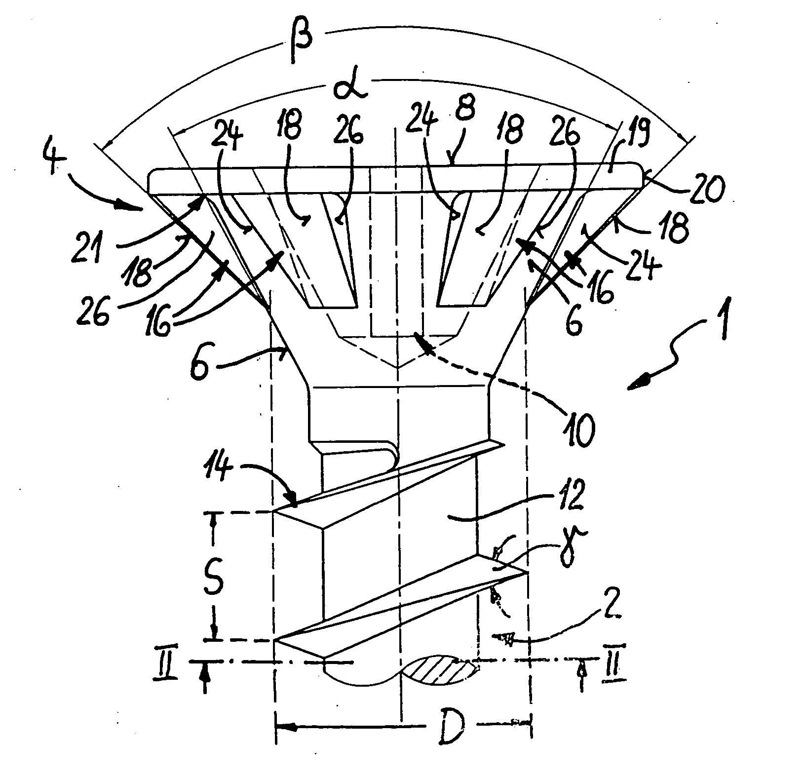
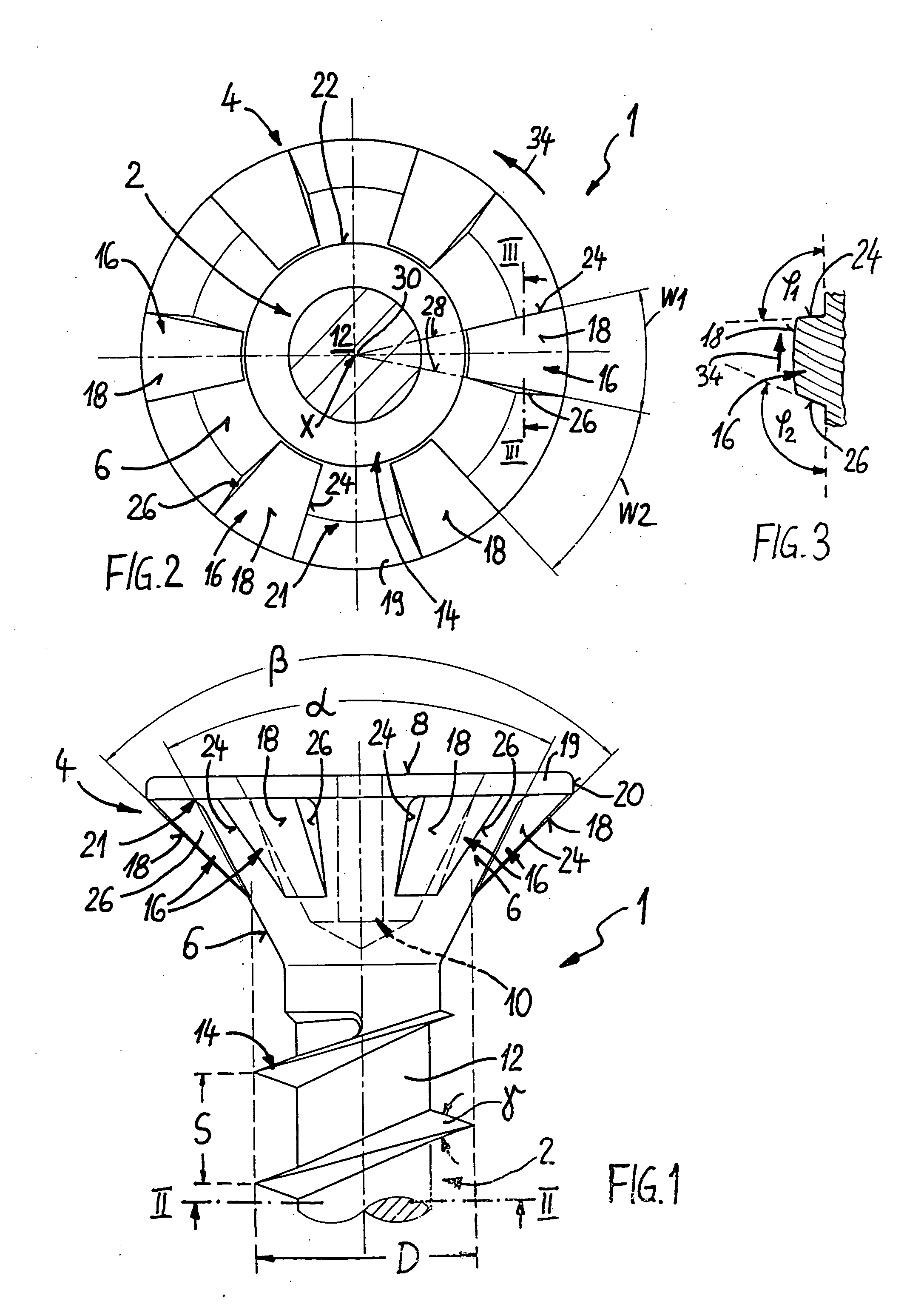
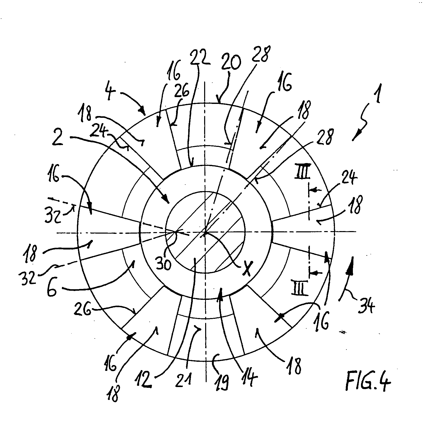
"The present invention is about a new type of countersunk screw that can be used for both direct screwing into wood and for fastening components with countersunk mounting holes. The screw has a conical surface with rib-like protrusions that are distributed over the periphery of the screw. These protrusions are designed to have a certain surface pressure when the screw is tightened, which prevents damage to the component and ensures a high retaining force. The screw also has a relatively small countersinking angle, which is beneficial for direct screwing into wood and for fastening components with countersunk mounting holes having a countersinking angle of around 90 degrees. Overall, this new screw design has good usage characteristics and can be used for a wide range of applications."

Problems solved by technology

These screws are not, however, suitable for fastening components with 90° sinkholes, since they do not come to bear with a sufficiently large area in the sinkhole, which is also detrimental to the fastening of the component.
This screw is not therefore suitable for fastening fittings or the like with 90° sinkholes since the ribs would in this case cause surface damage with their countersinking cutters and would make an impression with their very narrow surfaces.

Method used


Image

  • Countersunk screw
  • Countersunk screw
  • Countersunk screw

Examples


Embodiment Construction

[0014] A countersunk screw 1 according to the invention has a threaded shank 2 with a countersunk head 4. At the other end, the threaded shank 2 passes into a screw tip (not represented). The countersunk head 4 has a conical surface 6 tapering at a certain countersinking angle α in the direction of the threaded shank 2.

[0015] In the represented illustrative embodiment, the countersunk head 4 is constituted by a flat countersunk head, which, on its side opposite to the threaded shank 2, has a plane surface 8. Alternatively, the countersunk head 4 can also, however, be realized as a so-called raised head with a convexly curved surface. In both cases, the countersunk head 4 can preferably have a force application socket 10. Indicated in dashed representation in FIG. 1, this is especially in the form of a cross recess or a star-shaped insert, preferably with key guide.

[0016] The threaded shank 2 comprises an at least segmentally cylindrical core 12 and a single-start or multiple-start...


PUM


Abstract

The invention relates to a countersunk screw having a threaded shank and a countersunk head, which latter has a conical surface tapering at a countersinking angle in the direction of the threaded shank. The conical surface has a plurality of ribbed protrusions distributed over the periphery and jointly defining a conical enveloping surface with a cone angle. The countersinking angle of the conical surface is less than the cone angle of the ribbed protrusions. The ribbed protrusions have outer bearing surfaces, which define the conical enveloping surface and which, in terms of their areal size, are dimensioned in dependence on a material-specific surface pressure such that, in a screw application for fastening fittings or the like by screwing into a sinkhole between the ribbed protrusions and the respective sinkhole, a certain, surface-damage-preventing surface pressure is generated. The ribbed protrusions are additionally designed such that, in a screw application involving direct, countersinking screwing into a soft material, such as, in particular, wood, they have a milling effect.

Description

CROSS-REFERENCE TO RELATED APPLICATION [0001] This application claims priority to German Utility Model Application filed Sep. 5, 2003. BACKGROUND OF THE INVENTION [0002] The present invention relates to a countersunk screw having a threaded shank and a countersunk head, which latter has a conical surface tapering at a countersinking angle in the direction of the threaded shank. The conical surface has a plurality of ribbed protrusions distributed over the periphery and jointly defining a conical enveloping surface with a cone angle, the countersinking angle of the conical surface being less than the cone angle of the ribbed protrusions. SUMMARY OF THE INVENTION [0003] Countersunk screws are known in numerous forms. The countersunk head can be configured as a flat or raised countersunk head. Such screws are used, on the one hand, to fasten fittings or like components, especially metal, the respective component having for each screw a countersunk mounting hole. The countersinking angl...

Claims


Application Information

Patent Timeline
Patent Type & Authority Applications(United States)
IPC IPC(8): F16B35/06
CPCF16B35/065
Inventor DICKE, ROBERT
Owner SPAX INT
Learn More