Optical disc device

a technology of optical discs and optical discs, applied in the field of optical disc devices, can solve the problems of deteriorating reproduction quality, inability to maintain recording quality at high-speed recording, and achieve the effects of improving the range and purpose of prml signal processing methods, stable and satisfactory reproduction quality, and improving reproduction quality

Inactive Publication Date: 2005-03-24
PANASONIC CORP
View PDF2 Cites 43 Cited by
  • Summary
  • Abstract
  • Description
  • Claims
  • Application Information

AI Technical Summary

Benefits of technology

[0015] The present invention provides an optical disc device which can obtain a stable reproduction quality without being affected by the recording quality, not only when the SNR (signal to noise ratio) of the reproduction signal is low, and when the jitter components of the reproduction signal are large, and when the quality of the reproduction signal is deteriorated depending on the tilt angle which is defined by the angle between the axis perpendicular to the recording surface of the optical disc medium and the axis of the incoming laser light, but also for optical reproduction signals which are reproduced from a medium on which a mark of an imperfect shape is generated, a medium including a birefringence for the light irradiated from the optical reproduction means, or a medium in which the asymmetry of the reproduction signal is extremely large.

Problems solved by technology

However, there are some cases where the reproduction quality is deteriorated by the PRML signal processing method with respect to an optical reproduction signal which is reproduced from a medium on which a mark of an imperfect shape is generated due to the recording performance, a medium which contains a birefringence with respect to an irradiated light from the light reproduction means, and a medium in which vertical asymmetry (hereinafter, referred to as asymmetry) of a reproduction signal is quite large, more than by the level judging method of performing the binary judgement at a slice level at which a balance of the recording code is achieved.
Further, since the mark shape at the recording is remarkably deteriorated more as the recording speed is increased, it is impossible to maintain the recording quality at the high-speed recording.

Method used


Image

  • Optical disc device
  • Optical disc device
  • Optical disc device

Examples


embodiment 1

[0073] [Embodiment 1]

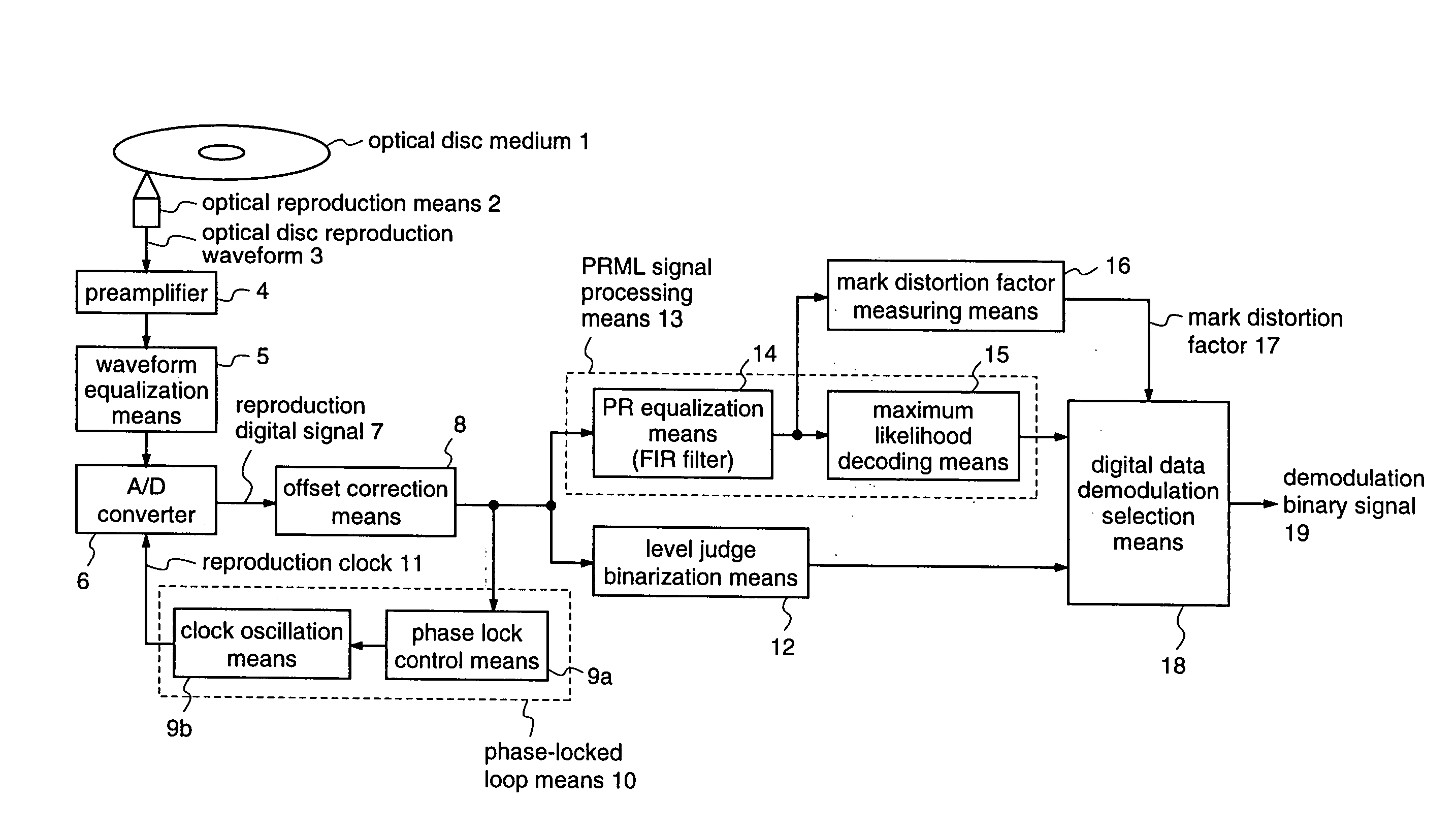
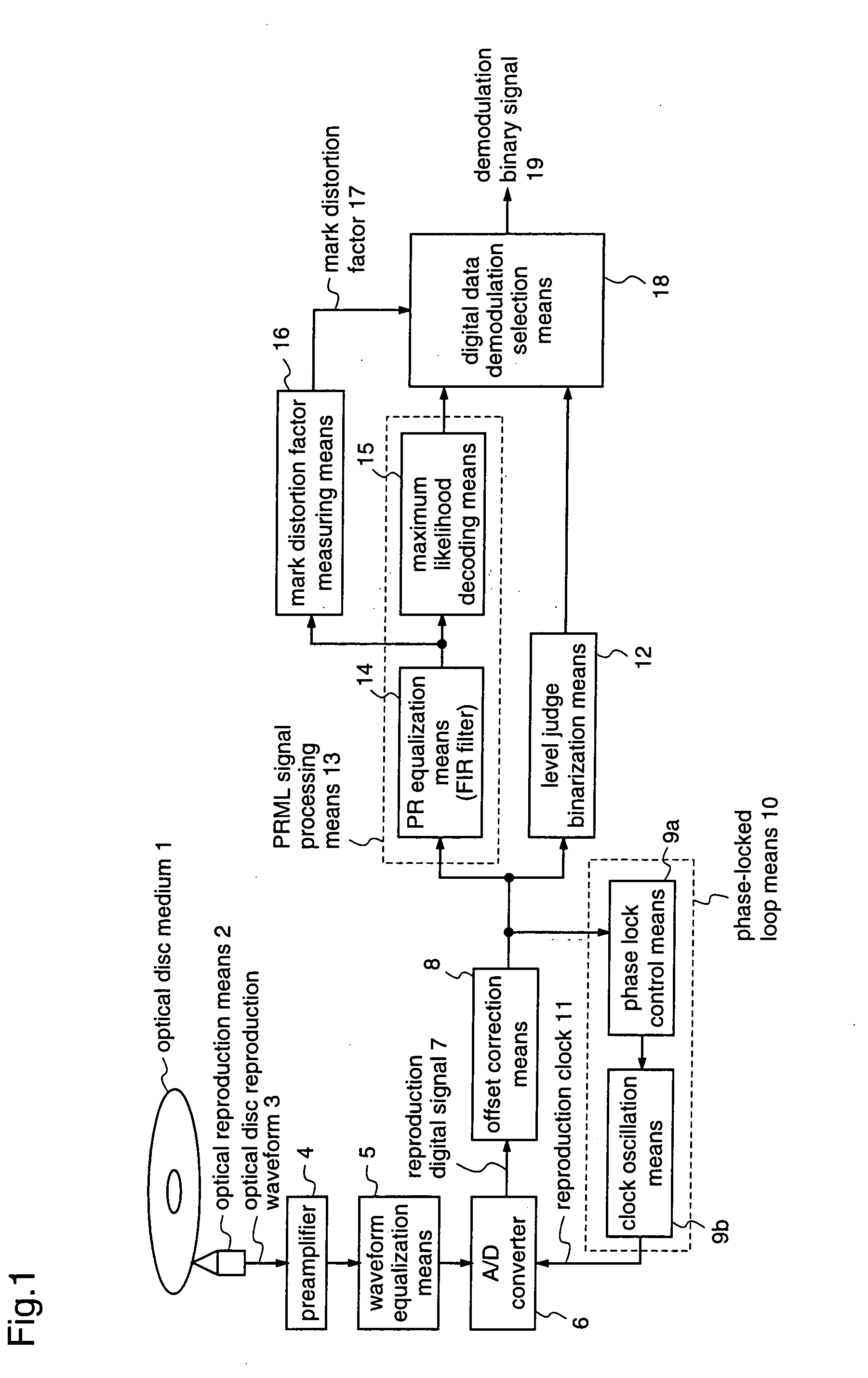
[0074]FIG. 1 is a block diagram illustrating a structure of an optical disc device according to a first embodiment of the present invention.

[0075] This first embodiment corresponds to claims 1, 3 to 7, 9, 10 and 13. This embodiment provides an optical disc device which, when playing back an optical disc, obtains a binary output by synchronizing a channel bit signal and a channel bit clock using a PLL, to obtain a reproduction signal from the channel, and performing the PRML signal processing to the reproduction signal or judging the signal at a slice level, in which one of the PRML signal processing method and the level judging method is selected as a means for demodulating digital data by measuring a distortion factor of a reproduction waveform which is caused by an imperfect shape of a mark recorded on an optical recording medium, thereby enabling to obtain a stable reproduction quality without being affected by the recording quality.

[0076] In FIG. 1, the sa...

embodiment 2

[0102] [Embodiment 2]

[0103]FIG. 9 are block diagrams illustrating a structure of an optical disc device according to a second embodiment of the present invention.

[0104] The second embodiment corresponds to claims 1, 2, and 14. This embodiment enables to adapt a threshold value for a metric operation in the maximum likelihood decoding means 15 of the PRML signal processing method as a means for demodulating digital data, by measuring a factor of distortion in a reproduction waveform which occurs due to an imperfect shape of the mark recorded on an optical recording medium 1, thereby to improve a mark-distortion resistant property of the PRML signal processing method. Accordingly, this embodiment provides a more stable reproduction quality without being affected by the recording quality, as compared to the first embodiment.

[0105] In FIG. 9a, the same reference numerals as those in FIG. 1 denote the same or corresponding elements. Threshold control information 67 is generated by the ...

embodiment 3

[0116] [Embodiment 3]

[0117]FIG. 11 are block diagrams illustrating a structure of an optical disc device according to a third embodiment of the present invention.

[0118] The third embodiment corresponds to claims 8, 12 and 15. In this third embodiment, in addition to the function as described in the second embodiment, a function of performing correction on the basis of the output signal from the level judge binarization means 12, when the mark distortion is extraordinarily large and the reproduction signal crosses the center level at the central part of the mark in the reproduction signal is added, thereby obtaining a more stable reproduction quality than in the second embodiment, without being affected by the recording quality.

[0119] In FIG. 11a, a detection error flag 70 is generated when the mark distortion factor measuring means 16 cannot detect a mark pattern having a long recording width as a detection object in cases where the mark distortion is extraordinarily large and the...


PUM


Abstract

An optical disc device of the present invention obtains a reproduction quality that is independent of a mark distortion by receiving a signal that is obtained from an A / D converter for digitizing a reproduction signal of an optical disc medium and an offset correction means for performing offset correction, accurately measuring a mark distortion factor in a mark pattern having a long recording width by means of a mark distortion factor measuring means, and selecting one of output signals from a PRML signal processing means and a level judge binarization means by means of a digital data demodulation selection means by utilizing the measured mark distortion factor as a judgement criterion, to be used as a demodulation binary signal.

Description

FIELD OF THE INVENTION [0001] The present invention relates to optical disc devices for reproducing data which are digitally recorded on an optical disc medium and, more particularly, to optical disc devices which can be suitably utilized in cases of reproducing data on a recording-type medium containing an imperfect recording mark or a large asymmetry, or a medium containing a birefringence. [0002] More specifically, this invention relates to a read channel technology of performing signal processing to an optical reproduction waveform of an optical disc device to read a clock that is synchronized with frequency components of the optical reproduction waveform and a recorded binary signal and, more particularly, to an improved read channel technology for improving a reproduction quality which will be deteriorated depending on recording media, recording qualities, and reproduction mechanism, using a digital data demodulation means such as a PRML (partial response maximum likelihood) s...

Claims


Application Information

Patent Timeline
IPC IPC(8): G11B5/09G11B7/00G11B20/10G11B7/005G11B20/14
CPCG11B20/10009G11B20/10296G11B20/10203G11B20/10055G11B20/10
Inventor OGURA, YOUICHI
Owner PANASONIC CORP
Why Eureka
Try Eureka