Optical information recording apparatus
a technology of optical information and recording apparatus, which is applied in the direction of data recording, instruments, optical beam sources, etc., can solve the problems of not being able to accurately locate the optimal point, and achieve the effect of reducing waiting time, accurate optimization, and raising the reliability of the readout signal
- Summary
- Abstract
- Description
- Claims
- Application Information
AI Technical Summary
Benefits of technology
Problems solved by technology
Method used
Image

Examples
embodiment 1
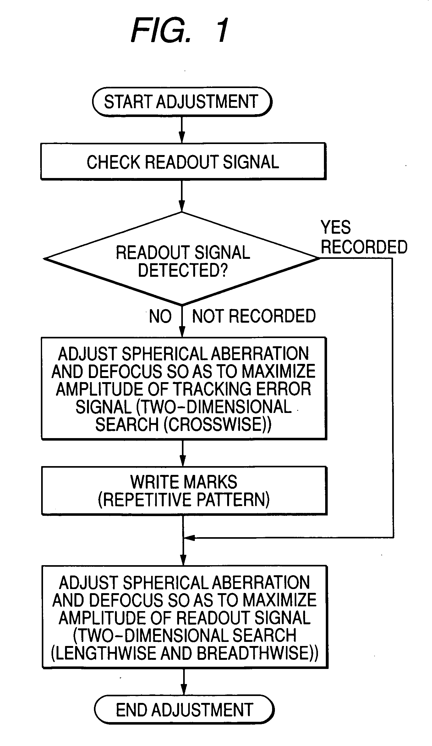
Spherical Aberration / Defocus Adjustment Method for Rewritable Optical Disk
With reference to FIGS. 1 through 7, the following describes the general configuration of an optical disk apparatus (optical information recording apparatus) provided with a spherical aberration correcting function according to the present invention.
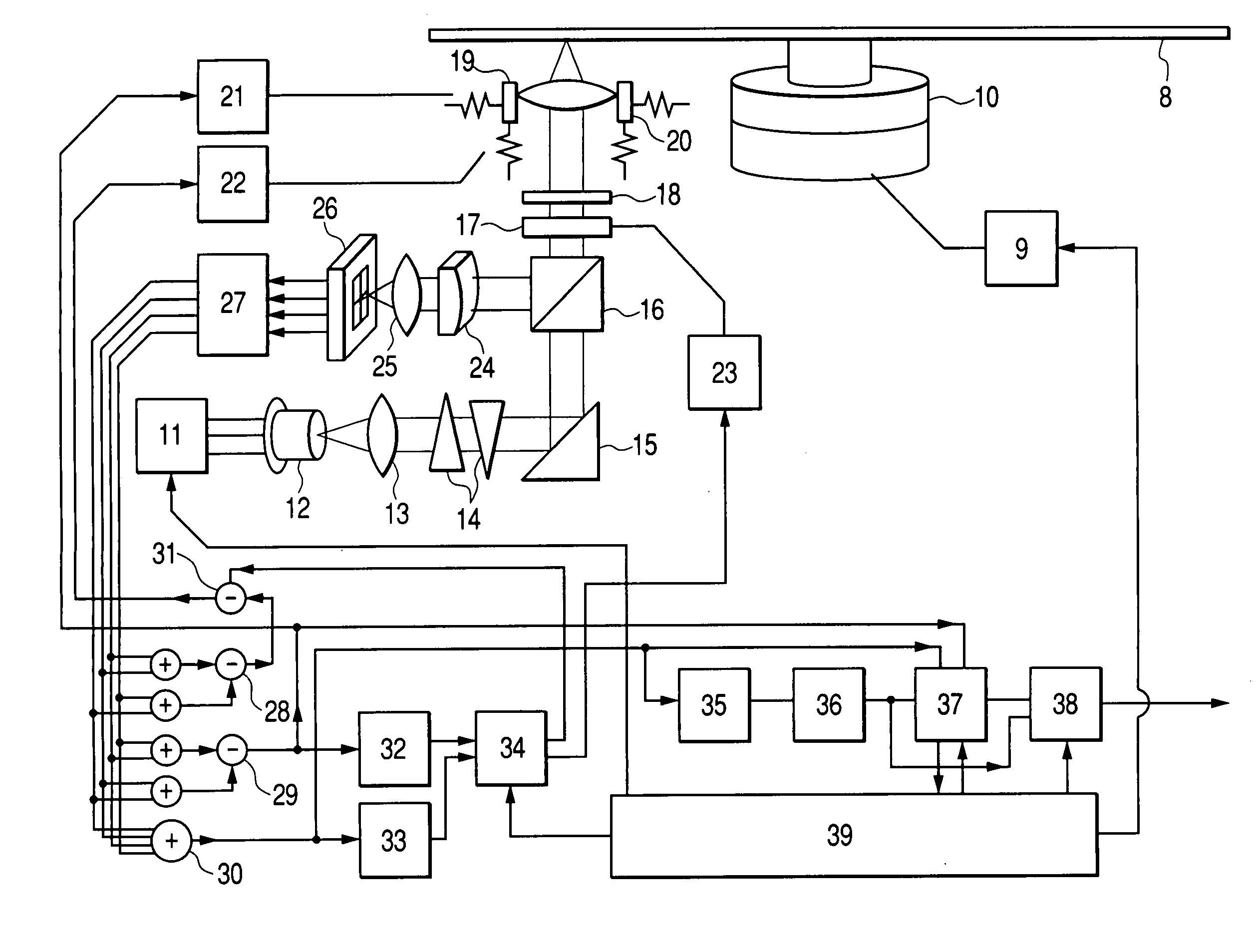
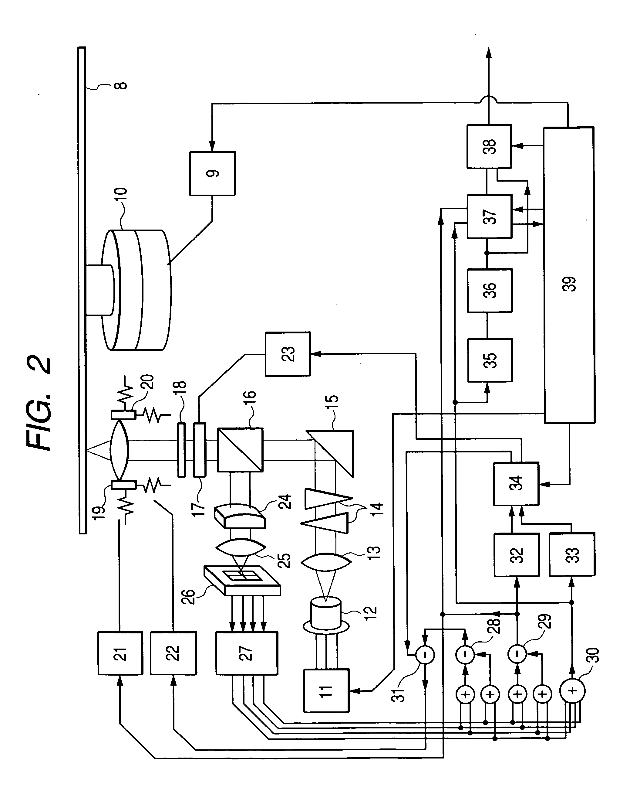
Firstly, FIG. 2 shows the general configuration of an optical disk apparatus (optical information recording apparatus) provided with a spherical aberration correcting function according to the present invention.
(General Configuration of Optical System)
An optical disk 8 or a recording medium is mounted on a motor 10 whose rotation speed is controlled by a rotation servo controller 9. A laser diode 12 driven by a laser driver 11 irradiates this medium with light. After having passed through a collimating lens 13 and a beam-shaping prism 14, light from the laser diode 12 is guided toward the disk 8 by a reflecting mirror 15 which changes the direction of the ...
embodiment 2
Two-Dimensional Search Method
An example of a two-dimensional search procedure for spherical aberration / defocus adjustment according to the present invention is described below with reference to FIGS. 8 through 15.
(Two-Dimensional Search Method for Tracking Error Signal Amplitude)
With reference to FIGS. 8 through 11, the following describes a procedure for maximizing the amplitude of the tracking error signal.
Firstly, FIG. 8 shows an enlarged central part of the tracking error signal's amplitude distribution shown in FIG. 3. FIG. 8 is depicted as a contour map. Note that as compared with FIG. 3, the axis of the spherical aberration is given opposite signs and therefore apparent slopes are opposite.
As mentioned in the description of the first embodiment, the distribution of the tracking error signal amplitude as a function of the spherical aberration and the defocus resembles a mountain chain having a peak elongated in an oblique direction. Therefore, the highest level for ...
embodiment 3
(Adjustment of Spherical Aberration by Using Interpolative Values)
With reference to FIGS. 2 and 16 through 21, the following describes configurations of optical information recording apparatus that correct spherical aberration for a recording medium having a transparent layer whose thickness varies from place to place on the medium.
(Correction for Single Recording Layer, or One and the Same Recording Layer)
Firstly, referring to FIGS. 16 and 17, the following describes the configuration of an optical information recording apparatus that corrects the spherical aberration so as to compensate for the thickness error of the transparent layer formed on the recording medium. It is assumed either that the recording medium has a single recording layer or that the recording medium has plural recording layers but correction is made for one of them.
FIG. 16 shows a recording disk medium having a single recording layer. A spherical aberration adjustment procedure, shown in FIG. 17 (flowch...
PUM
| Property | Measurement | Unit |
|---|---|---|
| density | aaaaa | aaaaa |
| thickness | aaaaa | aaaaa |
| wavelength | aaaaa | aaaaa |
Abstract
Description
Claims
Application Information
 - R&D
- Intellectual Property
- Life Sciences
- Materials
- Tech Scout
- Unparalleled Data Quality
- Higher Quality Content
- 60% Fewer Hallucinations
Browse by: Latest US Patents, China's latest patents, Technical Efficacy Thesaurus, Application Domain, Technology Topic, Popular Technical Reports.
© 2025 PatSnap. All rights reserved.Legal|Privacy policy|Modern Slavery Act Transparency Statement|Sitemap|About US| Contact US: help@patsnap.com