Arrangement and a method for emitting light
a technology of cathodoluminescent light source and arrangement method, which is applied in the direction of gas discharge lamp, fixed installation, discharge tube screen, etc., can solve the problem of prolonging the life of the lamp, and achieve the effect of ensuring the dimming
- Summary
- Abstract
- Description
- Claims
- Application Information
AI Technical Summary
Benefits of technology
Problems solved by technology
Method used
Image

Examples
first embodiment
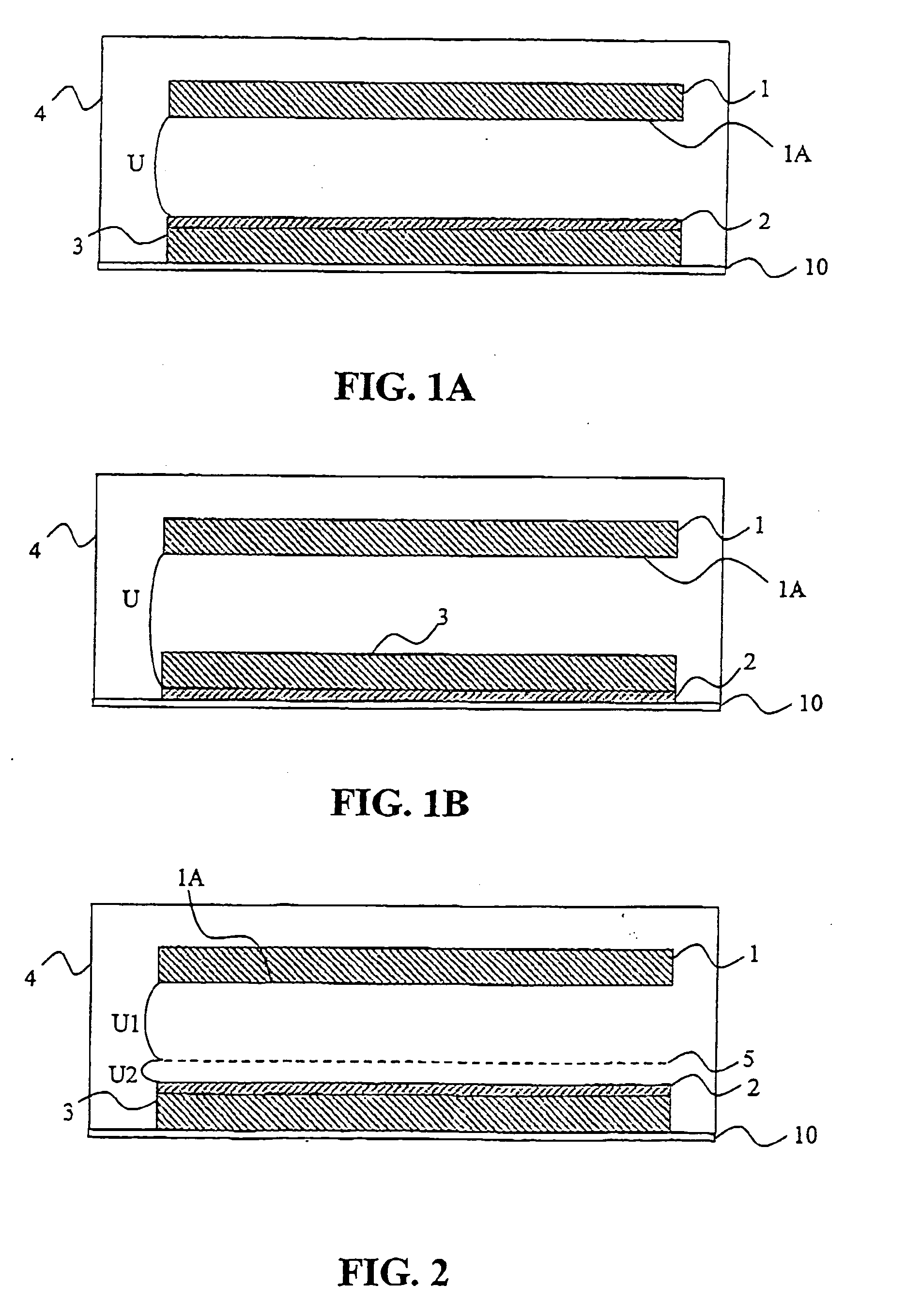
[0015] the present invention will now be described with reference to FIGS. 1A and 1B.
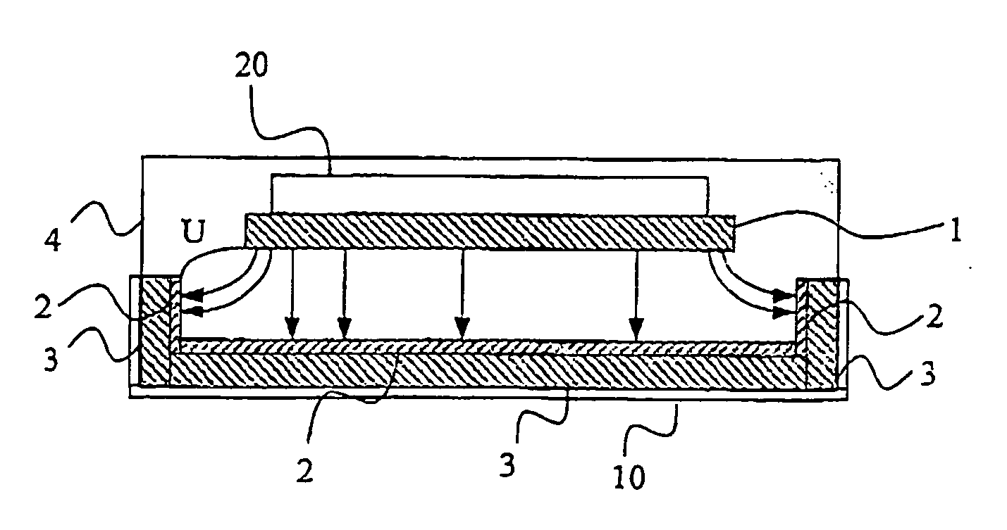
[0016] A planar cathodoluminescent light source comprises a planar cathode 1, a planar anode 2 parallel to the cathode 1 and a fluorescent layer 3 inside a casing 4. The casing 4 has a window 10 to allow light to emerge from the light source. The fluorescent layer 3 is arranged on the inside of the window 10, and the anode 2 is arranged on a surface of the fluorescent layer 3, which faces the cathode 1.
[0017] The casing 4 is hermetically sealed and filled with a gas suitable for electron avalanche amplification. A diffuser may be arranged outside the casing 4 (not illustrated). A diffuser provides leveling of luminous intensity to compensate for different luminous intensity from different areas of the light source.
[0018] The planar cathode 1 may be any type of cathode that can be stimulated to emit electrons from its surface 1A facing the anode 2. It may have a smooth or an irregular surface. Irre...
fourth embodiment
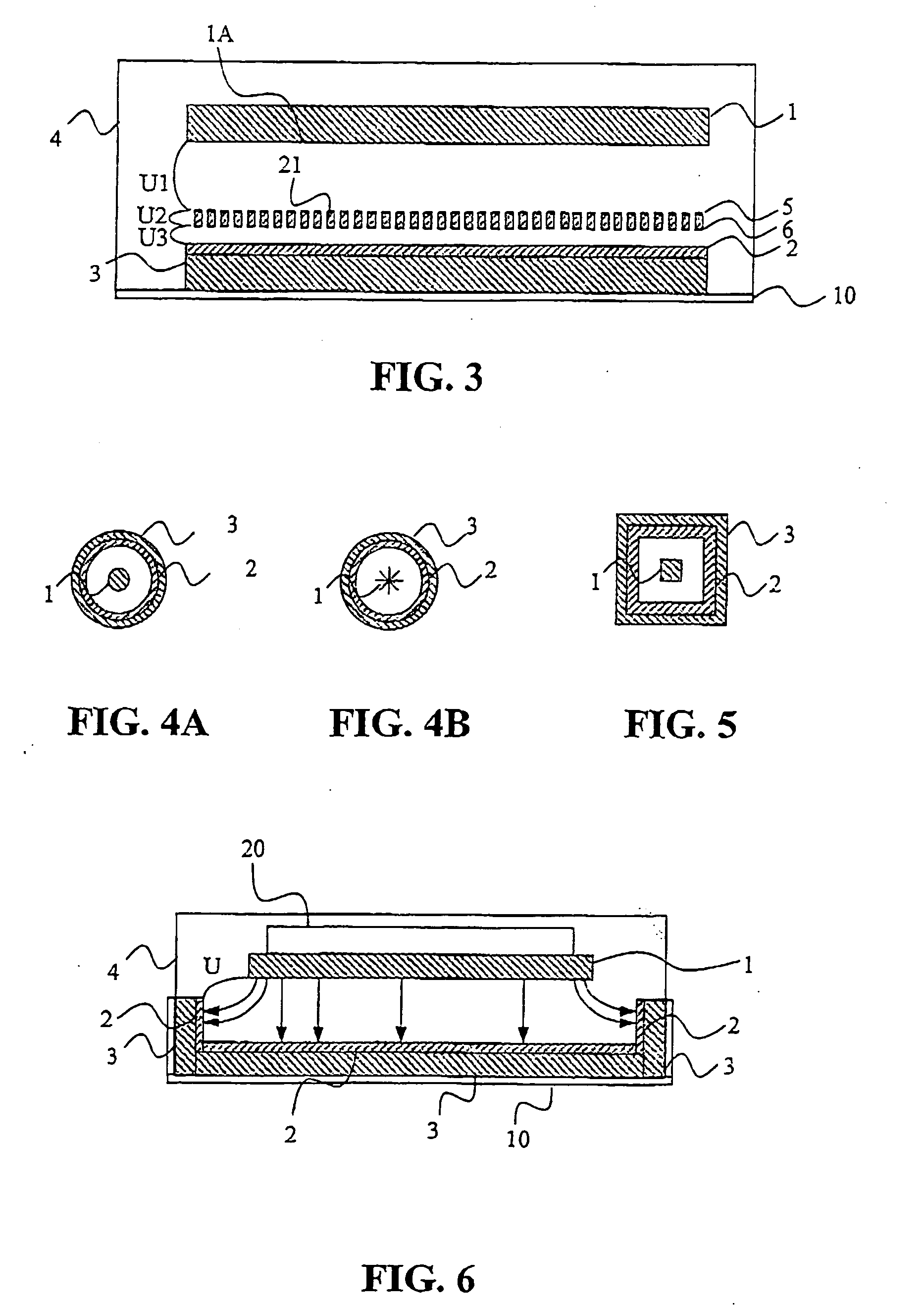
[0039] the present invention will next be described with reference to FIGS. 4A and 4B.
[0040] A cylindrical cathodoluminescent light source comprises a rod cathode 1 having a circular cross section, a cylindrical anode 2 having an annular cross section and a cylindrical fluorescent substance 3 inside a casing (not illustrated). The casing has a window to allow light to emerge from the light source. The fluorescent layer 3 may be arranged to cover the inside of the window. The anode 2 is preferably arranged on the cylindrical fluorescent substance 3 facing the cathode 1.
[0041] The casing is hermetically sealed and filled with a gas suitable for electron avalanche amplification. A diffuser (not illustrated) may be arranged outside the casing, to provide leveling of luminous intensity to compensate for different luminous intensity from different areas of the light source.
[0042] The rod cathode 1 may have a surface similar to the cathode surface described above in connection with the f...
fifth embodiment
[0054] Another design of lamp housing is illustrated in FIG. 8, and includes a lamp fitting part 7 and a glass part 8. The lamp fitting part 7 is arranged to hold a light source as e.g. the fourth or fifth embodiment in the lamp housing and the lamp housing. The glass part 8 is transparent, translucent or non-transparent radial to an axis of symmetry of the cylinder and open upwards and / or downwards.
[0055] Yet another design of lamp housing is illustrated in FIG. 9, and includes a lamp fitting part 7 and a glass part 8. The lamp fitting part 7 is non-transparent and arranged to hold a light source as e.g. the spherical alternative of the fourth embodiment in the lamp housing and the lamp housing to a ceiling. The glass part 8 is transparent or translucent.
[0056] All the embodiments described above may easily be provided with a dimmer. By varying a voltage applied to the light source the emission current and / or the avalanche amplification may be varied, which in turn varies the inte...
PUM
 Abstract
Description
Claims
Application Information
 - R&D
- Intellectual Property
- Life Sciences
- Materials
- Tech Scout
- Unparalleled Data Quality
- Higher Quality Content
- 60% Fewer Hallucinations
Browse by: Latest US Patents, China's latest patents, Technical Efficacy Thesaurus, Application Domain, Technology Topic, Popular Technical Reports.
© 2025 PatSnap. All rights reserved.Legal|Privacy policy|Modern Slavery Act Transparency Statement|Sitemap|About US| Contact US: help@patsnap.com