Lighting fixture

a technology of light fixture and dimming device, which is applied in the direction of fixed installation, lighting and heating apparatus, lighting support devices, etc., can solve the problems of difficult dimming control, laborious dimming control, and dangerous configuration of such a configuration

Inactive Publication Date: 2019-09-17
PANASONIC INTELLECTUAL PROPERTY MANAGEMENT CO LTD
View PDF2 Cites 1 Cited by
  • Summary
  • Abstract
  • Description
  • Claims
  • Application Information

AI Technical Summary

Benefits of technology

[0007]The present disclosure has been conceived to overcome the above problem, and has an object to provide a lighting fixture that can be easily controlled. For example, the dimming of the lighting fixture can be easily controlled.
[0009]According to the present disclosure, it is easy to control the lighting fixture, such as control the dimming of the lighting fixture.

Problems solved by technology

Thus, controlling the dimming with such a configuration is not only laborious but dangerous as the user needs to posture his or her body upward in order to adjust the dimming.
Thus, conventional spotlights are problematic in that controlling the dimming is difficult.

Method used


Image

  • Lighting fixture
  • Lighting fixture
  • Lighting fixture

Examples


embodiment

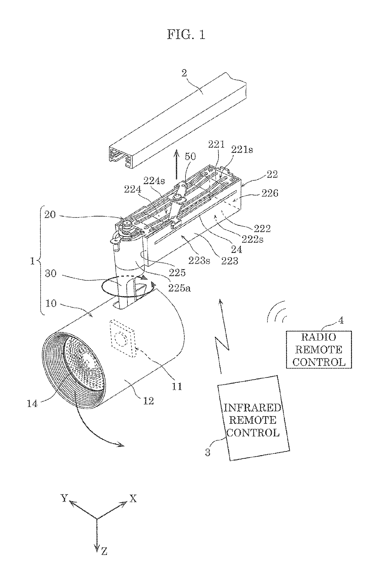
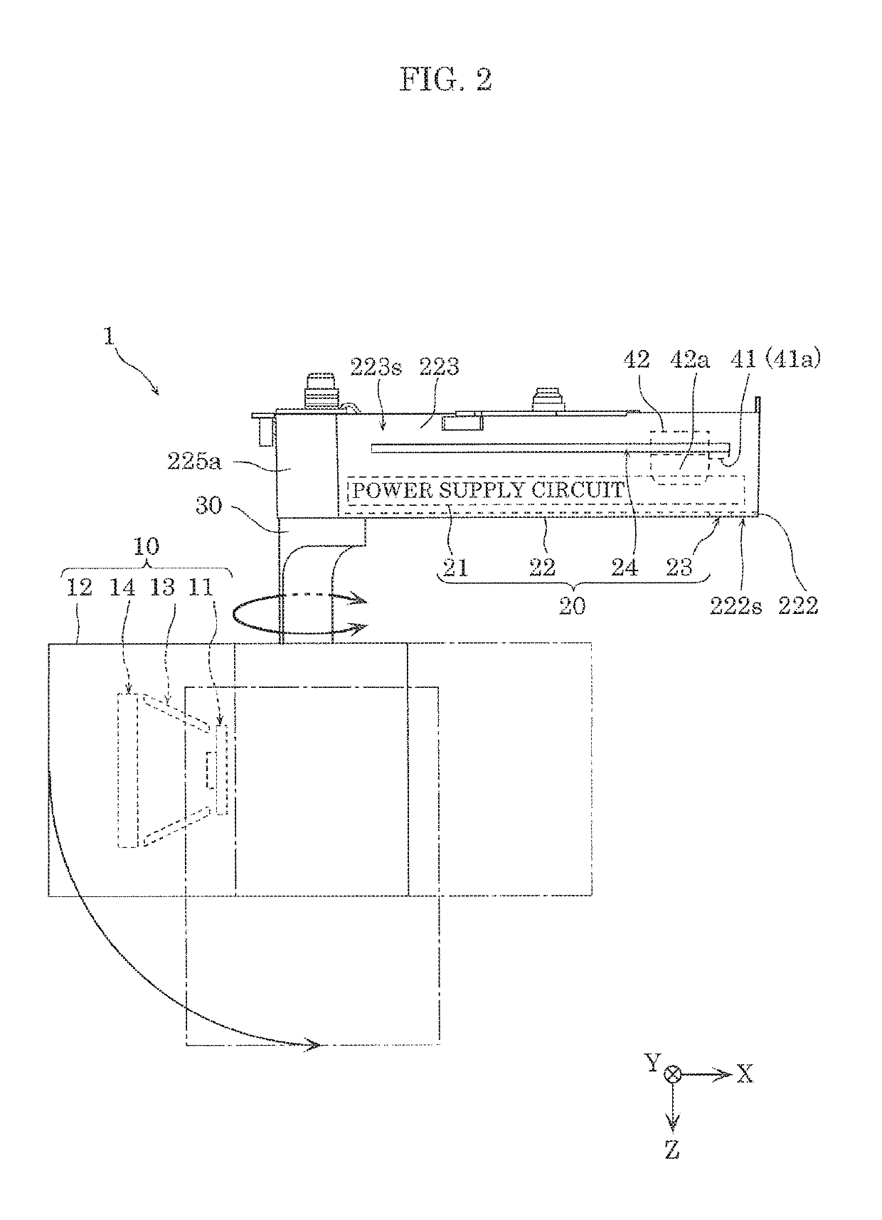
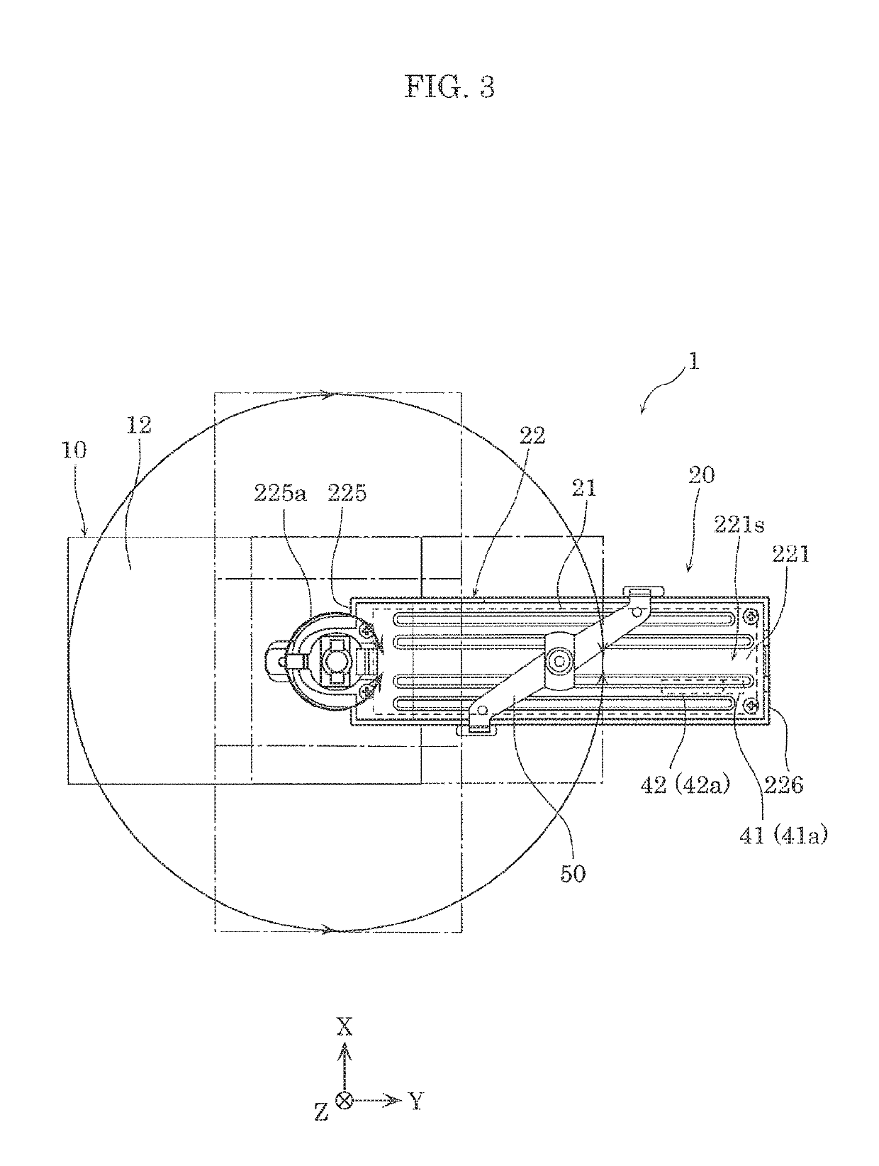
[0029]First, lighting fixture 1 according to an embodiment will be described with reference to FIG. 1 through FIG. 5. FIG. 1 is a perspective view of lighting fixture 1 according to this embodiment. FIG. 2 is a side view of the same lighting fixture 1. FIG. 3 is a top view of the same lighting fixture 1. FIG. 4 is a bottom view of the same lighting fixture 1. FIG. 5 is a cross sectional view of the same lighting fixture 1, taken at line V-V in FIG. 4. Note that power supply circuit 21 is not illustrated in FIG. 5.

[0030]As illustrated in FIG. 1, lighting fixture 1 is, for example, a spotlight that is installed on, for example, lighting duct 2 (wiring duct), and includes lamp 10 that emits illumination light, power supply 20, and arm 30 that couples lamp 10 and power supply 20.

[0031]Lighting duct 2 is one example of an attachment component to which lighting fixture 1 attaches, and is installed on part of a building, such as, the ceiling, beam, or wall of a building. Lighting fixture 1...


PUM


Abstract

A lighting fixture for attaching to an attachment component is provided. A lamp includes a light source that emits illumination light. A power supply includes a power supply circuit that generates power for causing the light source to emit the illumination light and a power supply housing that houses the power supply circuit. An arm couples the lamp and the power supply and rotatably supports the lamp. The power supply housing houses an infrared communication receiver that receives an infrared signal for controlling the lighting fixture and a radio communication circuit that receives a radio signal for controlling the lighting fixture. The power supply housing includes a first opening through which the infrared communication receiver receives the infrared signal.

Description

CROSS REFERENCE TO RELATED APPLICATION[0001]This application claims the benefit of priority of Japanese Patent Application Number 2017-033949 filed on Feb. 24, 2017, the entire content of which is hereby incorporated by reference.BACKGROUND1. Technical Field[0002]The present disclosure relates to a lighting fixture such as a spotlight.2. Description of the Related Art[0003]A spotlight includes, for example, a lamp that emits illumination light, a power supply including a power supply box that houses a power supply circuit, and an arm that couples the lamp and the power supply (for example, see Japanese Unexamined Patent Application Publication No. 2014-146503).[0004]With this type of spotlight, the angles of the portion that couples the lamp and the arm together and the portion that couples the power supply and the arm together are freely adjustable. This makes it possible to freely change the orientation of the lamp and thus change the direction in which light is emitted from the l...

Claims


Application Information

Patent Timeline
Patent Type & Authority Patents(United States)
IPC IPC(8): H05B37/02F21V23/00F21V21/26F21V23/02F21V21/30F21V21/35F21V23/04F21Y115/10
CPCF21V21/35F21V21/30F21V21/26F21V23/008F21V23/045F21V23/023H05B37/0272F21Y2115/10F21S8/00F21V15/01F21V23/0435H05B47/19H05B47/195
Inventor SAKURAI, SATORUKOMATSU, NAOKIMATSUSHITA, KOJIOKADA, TOSHIZUMIIJICHI, RYOUSUKETANAKA, YUZURU
Owner PANASONIC INTELLECTUAL PROPERTY MANAGEMENT CO LTD
Why Eureka
Try Eureka