
Optical density-changing element, optical element and photographic unit

Inactive Publication Date: 2005-03-17
FUJIFILM HLDG CORP +1
View PDF5 Cites 11 Cited by
  • Summary
  • Abstract
  • Description
  • Claims
  • Application Information

AI Technical Summary

Benefits of technology

An object of the present invention is to provide an optical density-changing element capable of undergoing a change in optical density in response to an applied voltage, in particular an electrochromic element, the element having excellent performance of requiring only a small applied voltage for making it colored, showing a rapid response speed, and becoming completely bleached when restored to the bleached state from the colored state.
A further object of the invention is to provide an optical element which realizes a light amount control system capable of automatically controlling the amount of transmitted light over a wide range light amount range with a less loss of transmitted light due to the system itself and a rapid response speed.
The optical density-changing element of the present invention, particularly electrochromic element, has excellent properties of, for example, requiring only a small applied voltage to become in a colored state, responding at a high speed, and becoming completely bleached when restored to a bleached state from the colored state, and can undergo a rapid change in optical density in response to an applied voltage.
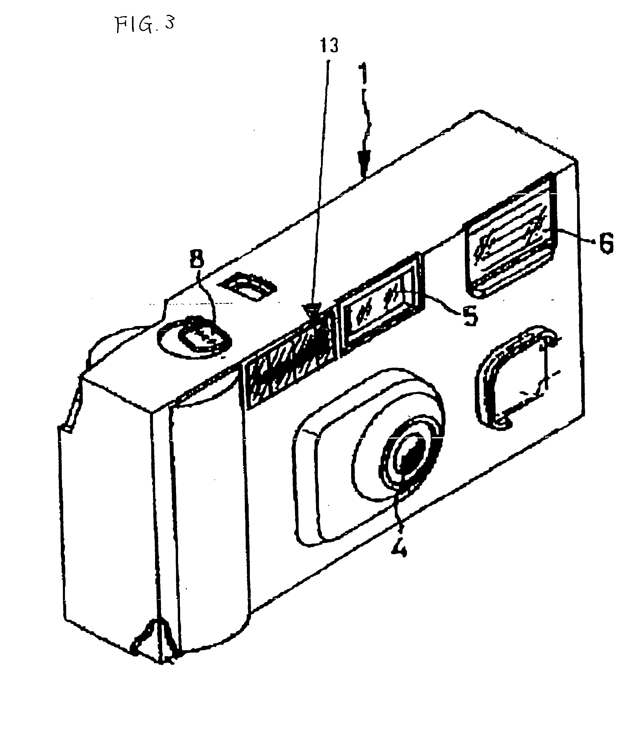
Also, according to the present invention, an illuminance range where photographing is possible can be expanded by loading on a film-with-lens or an electronic still camera an optical element capable of undergoing a change in optical density in response to an electromagnetic wave, particularly, an optical element wherein a solar cell capable of generating an electromotive force in response to, for example, an UV light or a visible light is connected to an electrochromic, light amount control filter capable of undergoing the change in optical density in response to the electromotive force.

Problems solved by technology

However, these materials show only a slow response speed, and their use has been limited.
In comparison with the electrochromism, however, thermochromism is slow in response speed and low in light transmission, and hence its use is limited, and its application to window materials for vehicles, display devices or camera-related optical elements involves difficulty.
However, since conventional film-with-lens units whose advantage is handiness are not equipped with an exposure-controlling mechanism, film-with-lens units loaded with a fast film often cause overexposure in a high intensity region, and thus their weak point of “being difficult to use” has been revealed.
However, it takes generally about one minute for the photochromic compound to become colored and takes longer than several ten minutes to become bleached (see, for example, Solid State and Material Science, 1990, 16, p.291), and thus it has been difficult to use the compound for a light amount control system for controlling the photographic light amount.
However, it is unavoidable, with the structure wherein the solar cell is layered on the electrochromic compound layer as in the above-mentioned proposal, for part of light passing through the electrochromic compound layer to be absorbed by the solar cell.
Therefore, it is inappropriate for a system which utilizes transmitted light as much as possible when photographing a scene not requiring light amount control, such as camera-related optical elements in particular.
As a result of intensive investigations on the electrochromic element utilizing the nanoporous electrode wherein (i) a material capable of releasing or receiving electrons (a material undergoing or not undergoing a change in optical density in a wavelength range of 400 to 700 nm as a result of release or receipt of electrons) is adsorbed on (ii) a nanoporous material, it has been found that the electrochromic element can show unfavorable performance depending upon combination of (i) material capable of releasing or receiving electrons and (ii) nanoporous material.
The term “unfavorable performance” as used herein means that a more voltage is required for making the electrochromic element colored, that the electrochromic element shows a slow response speed, or that the electrochromic element is not made completely bleached when restored to the bleached state, and some of the color remains.

Method used


Image

  • Optical density-changing element, optical element and photographic unit
  • Optical density-changing element, optical element and photographic unit
  • Optical density-changing element, optical element and photographic unit

Examples


example 1

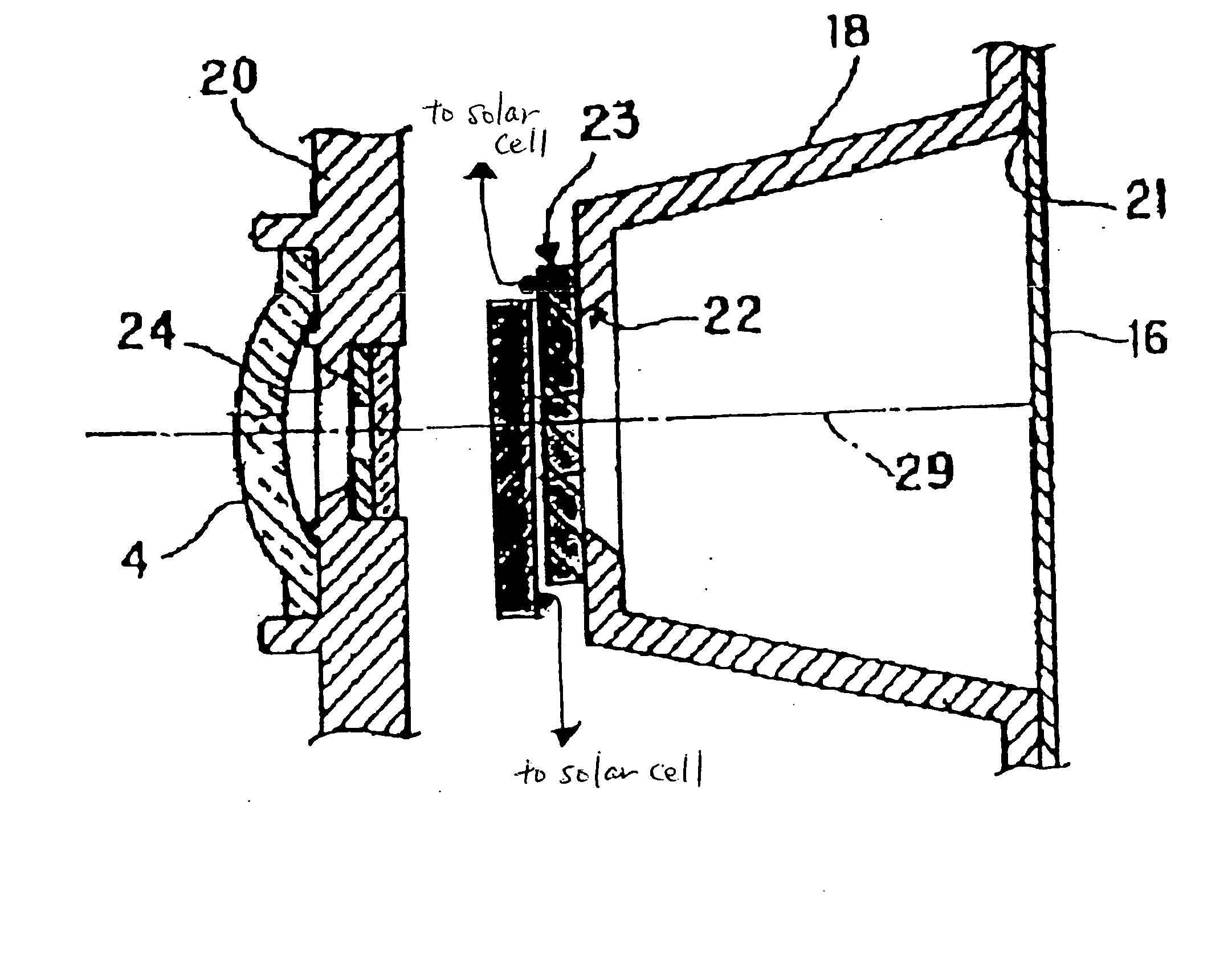
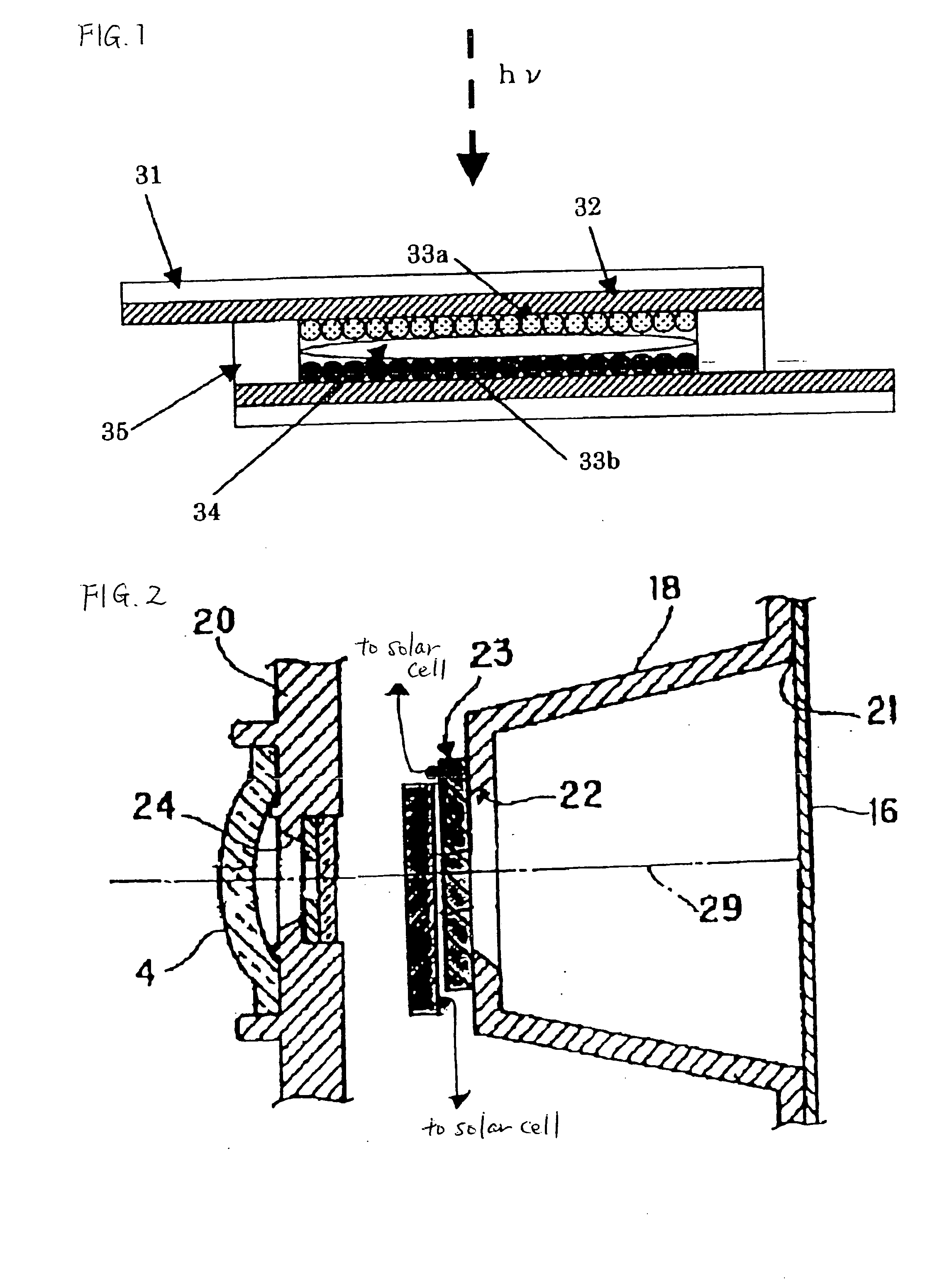
An electrochromic type optical density-changing element of the invention is described below. Its specific form is as shown in FIG. 1.

(1) Preparation of sample 101 (Example)

Sample 101 (Example) was prepared in the order of (i) preparation of a nanoporous tin oxide electrode for cathode, (ii) preparation of a nanoporous tin oxide electrode for anode, (iii) adsorption of a chromic dye and (iv) assembly of an electrochromic element. (i) Preparation of a nanoporous tin oxide electrode for cathode:

Polyethylene glycol (molecular weight: 20,000) was added to an aqueous dispersion of tin oxide having a diameter of about 40 nm, and the mixture was uniformly stirred to prepare a coating solution. As a coating plate, a 0.7-mm thick electrically conductive glass having coated thereon a conductive SnO2-evaporated thin film was used. Additionally, an antireflective film was provided on the opposite side of the transparent conductive glass to the conductive film-deposited side. On the conduc...

example 2

Sample 201 (present invention) and sample 202 (comparative example) as shown in Table 3, were prepared.

TABLE 3ChromicChromic MaterialMaterialon Cathode Side / on Anode Side / NanoporousNanoporousMaterial onFbc − ErMaterial onFba − EoSample No.Cathode Side(V)Anode Side(V)Sample 201V-1 / ZnO0.3 (∘)P-1 / SnO2−0.15 (∘)(presentinvention)Sample 202V-1 / V2O51.6 (x)P-1 / SnO2−0.15 (∘)(comparativeexample)

Properties of the sample 201 (present invention) and the sample 202 (comparative example) were examined. When a voltage of 1.5 V was applied to the sample 201 (present invention), an optical density at 610 nm increased by 1.0 within 30 seconds. Subsequently, the two electrodes were short-circuited, and the color was completely bleached within 20 seconds. On the other hand, when a voltage of 1.5 V was applied to the sample 202 (comparative example), an optical density at 610 nm increased by 0.5 after 30 seconds. Also, even when the two electrodes were short-circuited, it took 1 minute or longer for ...

example 3

Sample 301 (present invention) and sample 302 (comparative example) as shown in Table 5 were prepared.

TABLE 5ChromicChromic MaterialMaterialon Cathode Side / on Anode Side / NanoporousNanoporousMaterial onFbc − ErMaterial onFba − EoSample No.Cathode Side(V)Anode Side(V)Sample 301V-1 / SrTiO3  0.3 (∘)P-1 / SnO2−0.15 (∘)(presentinvention)Sample 302V-1 / ZrO2−1.0 (x)P-1 / SnO2−0.15 (∘)(comparativeexample)

Properties of the sample 301 (present invention) and the sample 302 (comparative example) were examined. When a voltage of 1.5 V was applied to the sample 301 (present invention), an optical density at 610 nm increased by 1.0 within 30 seconds. Subsequently, the two electrodes were short-circuited, and the color was completely bleached within 20 seconds. This is favor (rated as “O”) in view of controlling the electrochromic element. On the other hand, the sample 302 (comparative example) was colored even when no voltage was applied thereto, and an optical density at 610 nm increased. This is n...


PUM


Abstract

To provide an optical density-changing element which has excellent properties that it can be brought into a colored state by applying only a low voltage, that it shows a rapid response speed and becomes completely colorless when restored to a bleached state from the colored state, and which can undergo a change in optical density in response to an applied voltage, the optical density-changing element includes, on each of an anode and a cathode, a material capable of at least one of donating and accepting an electron and, as a result of at least one of donating and accepting the electron, undergoing a change in absorption spectrum in a visible region and a material undergoing substantially no change in absorption spectrum in the visible region, with potentials of these materials satisfying a specific relation defined in the specification.

Description

BACKGROUND OF THE INVENTION 1. Field of the Invention The present invention relates to an optical density-changing element which can undergo a change in optical density in response to an applied voltage, and which has excellent properties of, for example, requiring only a small applied voltage to become in a colored state, responding at a high speed, and being completely bleached when restored to a bleached state from the colored state. In particular, the present invention relates to an electrochromic element; an optical element comprising the optical density-changing element and an electromotive force-generating element capable of generating an electromotive force upon irradiation with an electromagnetic wave; and a photographic unit using the optical element. 2. Background Art Elements capable of undergoing a change in optical density in response to an electromagnetic wave find wide applications. Materials having the function of changing optical density in response to the elec...

Claims


Application Information

Patent Timeline
IPC IPC(8): G02B5/00G02F1/1503G02F1/155G03B7/095G03B9/02G03B15/05G03B17/04H01L31/04
CPCB82Y20/00G02F1/1508G02F1/1521G02F1/155G03B17/04G02F2202/36G03B7/095G03B9/02G03B15/05G02F2001/13324G03B2215/0503G03B2215/0507G02F1/1503G02F1/13324
Inventor KANEIWA, HIDEKISHINOHARA, RYUJIMATSUNAGA, ATSUSHIMORIMOTO, KIYOSHI
Owner FUJIFILM HLDG CORP
Learn More