Pressure sensor insert for a downhole tool

a technology of pressure sensor and downhole tool, which is applied in the field of pressure sensor insert, can solve the problems of inability to replace, repair or re-calibrate the pressure sensor in the field, and adversely affect the calibration of the pressure sensor, so as to enhance or facilitate the indirect transmission of ambient pressure and enhance or facilitate the effect of ambient pressur

Inactive Publication Date: 2005-03-17
OMEGA WELL MONITORING
View PDF12 Cites 43 Cited by
  • Summary
  • Abstract
  • Description
  • Claims
  • Application Information

AI Technical Summary

Benefits of technology

[0013] Further, in the preferred embodiment, the pressure sensor insert is configured such that it may be readily connected with and disconnected from the insert carrier. As a result, the pressure sensor insert may be removed and replaced in the field without the need to transport the entire insert carrier to the shop. The pressure sensor insert removed in the field may then be returned to the shop for repair or re-calibration, or simply disposed of. Accordingly, the manufacturing facility or machine shop need only maintain and calibrate an inventory of pressure sensor inserts, rather than the entire insert carrier. Further, the customer may keep one or more spare or replacement pressure sensor inserts on hand to further minimize any down time of the operation in the event of failure of the pressure sensor or the need for use of a different pressure sensor.
[0057] The insert may be comprised of an electrical power source for the electronics assembly. In this case, any suitable electrical power source may be used, such as a battery. However, preferably, an electrical power source is provided externally to the insert, such as by the insert carrier. Accordingly, the pressure sensor insert is preferably further comprised of an electrical connector for electrically connecting the insert with an electrical power source. Although the electrical connector may be located at any position within the housing of the insert, the electrical connector is preferably located adjacent to the second insert end. Thus, following the connection of the insert with the insert carrier, the electrical power source may be readily connected with the electrical connector at the second insert end.

Problems solved by technology

During use of the tool in the field, the pressure sensor may be exposed to conditions which either damage the pressure sensor or adversely affect the calibration of the pressure sensor.
As a result, repair or re-calibration of the pressure sensor may be required.
In each of these cases, the pressure sensor is not capable of being replaced, repaired or re-calibrated in the field.
During this period, the tool is unavailable for use which results in undesirable downtime for the tool and increased costs for the production or drilling operation.
However, none of these removable pressure sensors have been found to be fully satisfactory.
In addition, many pressure sensors used downhole have not been found to be fully satisfactory due to a proneness towards de-calibration and failure for several reasons.
First, repeated removal and replacement of the pressure sensor tends to stress a metal housing typically surrounding or enclosing at least a part of the pressure sensor which disturbs the calibration of the pressure sensor therein.
In addition, the handling of the pressure sensor during its removal and replacement may also adversely affect the calibration of the sensor.
Second, in use, the interior of the metal housing for the pressure sensor is typically exposed to high ambient pressure downhole.
Exposure of the pressure sensor to multiple pressure cycles tends to cause a stretching of the metal housing over time which also adversely affects the calibration of the pressure sensor.
However, the O-rings themselves are prone to failure and decrease the reliability of the tool and the pressure sensor in the field.
For instance, O-rings tend to corrode resulting in a tendency to fail.
As well, O-rings permit certain undesirable gases, such as carbon dioxide, to pass therethrough which may adversely affect the electronic components of the pressure sensor.

Method used


Image

  • Pressure sensor insert for a downhole tool
  • Pressure sensor insert for a downhole tool
  • Pressure sensor insert for a downhole tool

Examples


Embodiment Construction

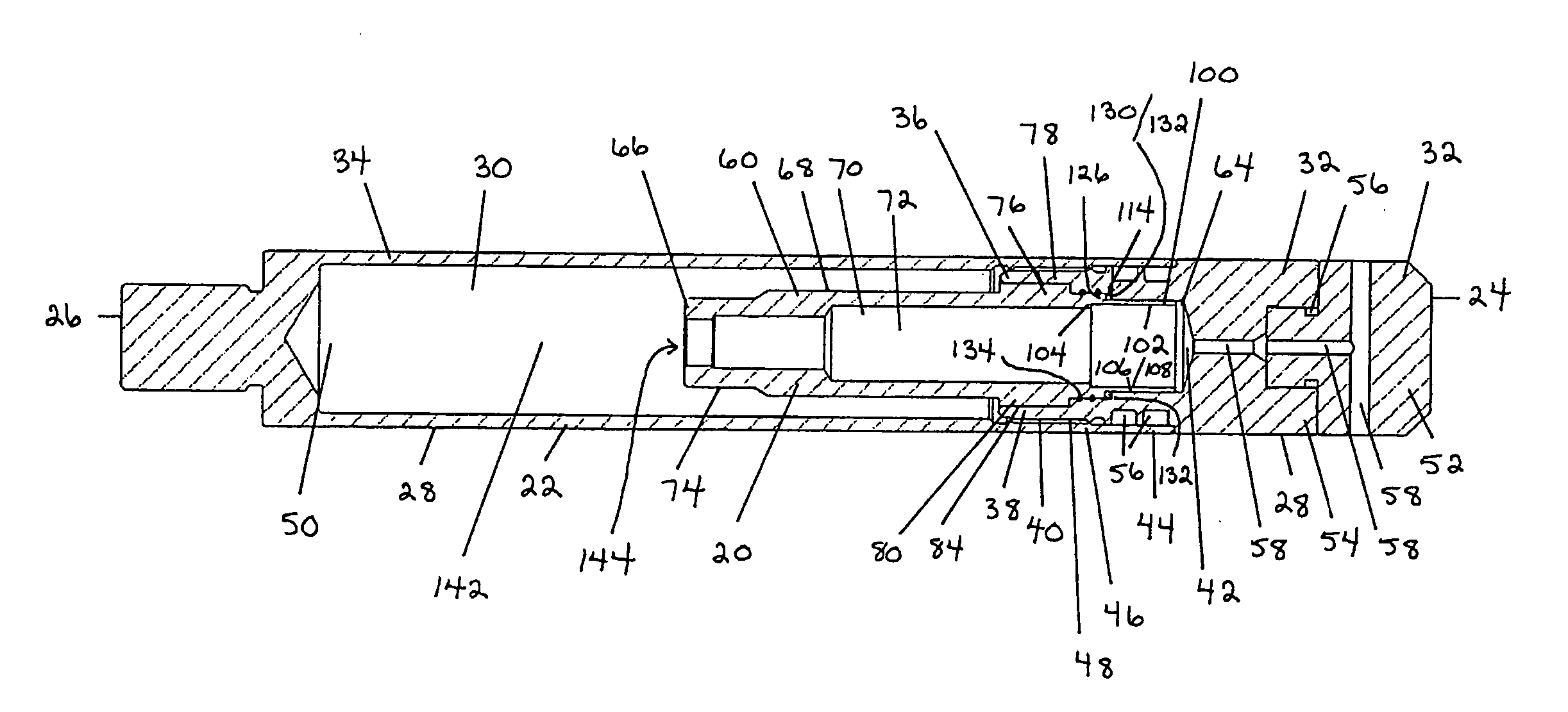
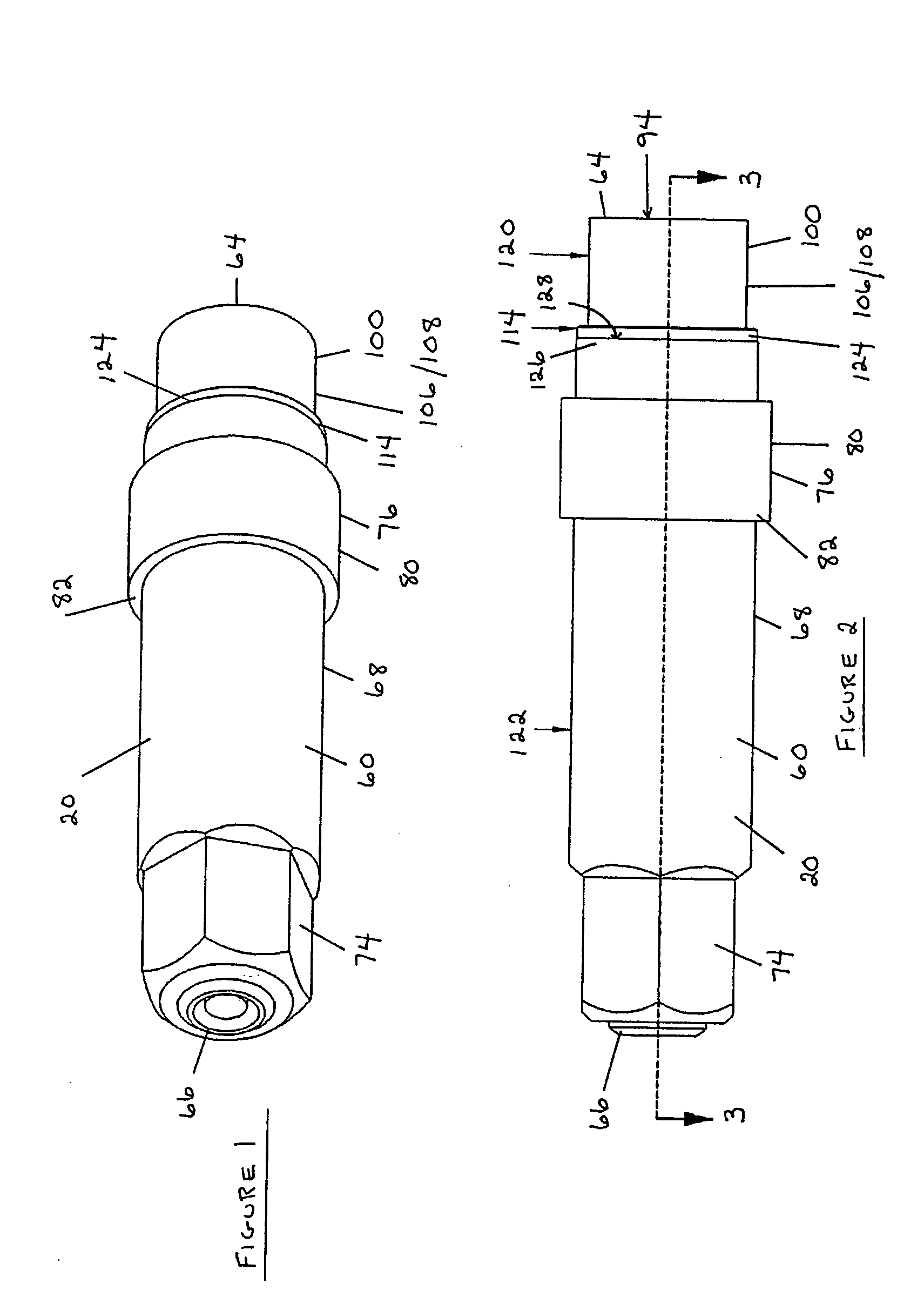
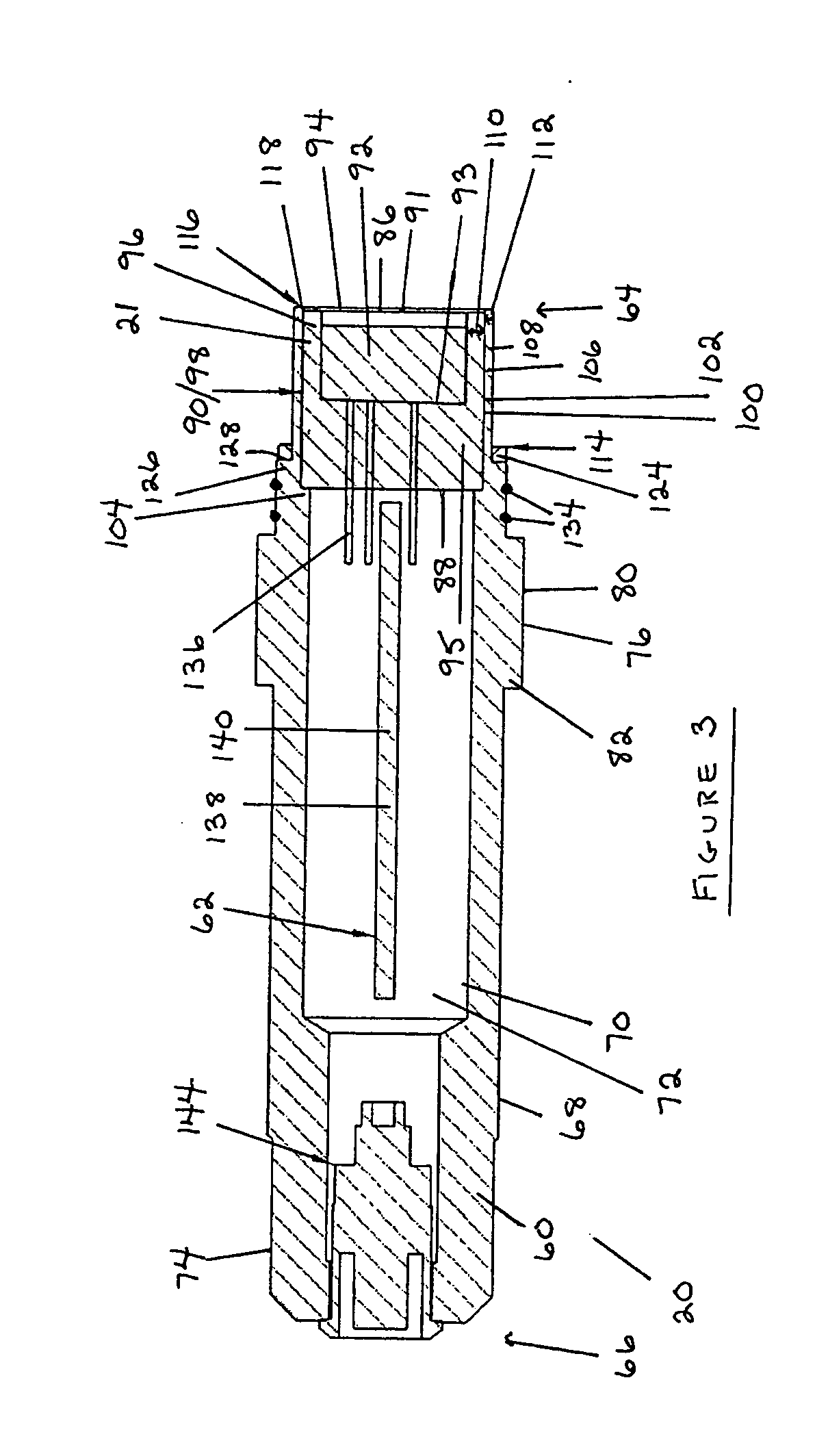
[0065] Referring to FIGS. 1-6, the present invention relates to a replaceable pressure sensor insert (20) comprised of a pressure sensor (21) for sensing ambient pressure, wherein the pressure sensor insert (20) is removably connectable with an insert carrier (22), as particularly shown in FIGS. 3-6. The insert carrier (22) may comprise all or a portion of any downhole drilling or production tool, apparatus or sub assembly where the use of a pressure sensor is required or desired for the particular operation being conducted. In other words, the downhole tool apparatus or sub assembly is comprised, at least in part, of the insert carrier (22). In the preferred embodiment, the downhole tool apparatus or sub assembly is comprised of the insert carrier (22) which is received within or connected with one or more further components, members or elements of the downhole tool apparatus or sub assembly.

[0066] Referring to FIGS. 3-6, the insert carrier (22) has a first carrier end (24) and a ...


PUM


Abstract

A replaceable pressure sensor insert adapted for removable connection with an insert carrier. The pressure sensor insert is comprised of a housing defining an exterior and an interior of the housing, a pressure sensor connected with the housing such that the pressure sensor is capable of sensing an ambient pressure at the exterior of the housing and an electronics assembly contained within the interior of the housing and electrically connected with the pressure sensor. In addition, the insert is comprised of a first insert mounting component adapted to be removably connectable with a second insert mounting component associated with the insert carrier in order to facilitate connection and replacement of the insert. Finally, a housing sealing mechanism is provided for sealing the insert relative to the insert carrier and a sensor sealing mechanism is provided for sealing the pressure sensor relative to the housing.

Description

FIELD OF INVENTION [0001] The present invention relates to a pressure sensor insert which is for use in a downhole tool or apparatus. More particularly, the invention relates to a replaceable pressure sensor insert which is adapted for removable connection with an insert carrier, which is preferably a downhole production or drilling tool or apparatus. BACKGROUND OF INVENTION [0002] Conventionally, pressure sensors or transducers are mounted within a desired downhole tool or apparatus which is custom built or designed to receive the pressure sensor. These pressure sensors are fixedly or non-removably mounted within the tool at the manufacturing facility or machine shop and shipped to the customer for use in the field. Accordingly, the pressure sensors are required to be calibrated in the shop prior to mounting within the tool. [0003] During use of the tool in the field, the pressure sensor may be exposed to conditions which either damage the pressure sensor or adversely affect the ca...

Claims


Application Information

Patent Timeline
Patent Type & Authority Applications(United States)
IPC IPC(8): E21B47/01E21B47/06
CPCE21B47/06E21B47/01
Inventor ZILLINGER, FRED
Owner OMEGA WELL MONITORING
Why Eureka
Try Eureka