Yarn false twist texturing apparatus

a texturing apparatus and yarn technology, applied in the field of yarn false twist texturing apparatus, can solve the problems of high friction in yarn, and achieve the effect of improving the wetting of yarn

Inactive Publication Date: 2005-03-17
SAURER GMBH & CO KG
View PDF6 Cites 5 Cited by
  • Summary
  • Abstract
  • Description
  • Claims
  • Application Information

AI Technical Summary

Benefits of technology

[0009] The metering of the cooling fluid by the rotatable cooling cylinder is preferably determined such that the cooling fluid fully evaporates when the yarn comes into contact with the cooling device. This ensures that the yarn advances into the downstream cooling device in an absolutely dry state, so that, for example, cooling rails or cooling tubes do not soil when the yarn advances over their surface. However, it is also possible to select the wetting of the yarn such that certain residual moisture remains in the yarn. This variant is applicable in particular in the case of cooling devices, which cool the yarn in a free cooling zone without contacting it. With that, it is possible to adjust on the yarn any degree of drying.
[0010] Further advantageous developments of the invention provide the advantage that the yarn friction is adjustable when the yarn is wetted. To this end, the cooling cylinder is operated by a drive unit that is preferably an electric motor. In this case, the cooling cylinder can be driven to rotate both in the direction of the advancing yarn and in the direction opposite to the advancing yarn. To obtain yarn frictions that are as low as possible, the cooling cylinder is driven to rotate in the same direction as the advancing yarn. This permits minimizing the yarn friction in a condition, in which the yarn and the yarn track of the cooling cylinder have the same speeds. To produce in other yarn types, for example, a higher yarn friction, it is also possible to drive the cooling cylinder to rotate in the opposite direction to the advancing yarn. The yarn and the yarn track thus move in opposite directions, which leads to a high friction in the yarn while being wetted. With the use of a controllable electric motor it is possible to realize irrespective of its wound direction of rotation, an adaptation of the circumferential speed of the cooling cylinder to any speed of the advancing yarn that is adjusted within the texturing zone.
[0014] A particularly advantageous development of the invention provides for arranging the heating device, the cooling cylinder, and the cooling device to form a substantially straight yarn path. With that, it is possible to form a texturing zone, in which additional yarn guide elements and thus frictions of the yarn are avoided.

Problems solved by technology

The yarn and the yarn track thus move in opposite directions, which leads to a high friction in the yarn while being wetted.

Method used


Image

  • Yarn false twist texturing apparatus
  • Yarn false twist texturing apparatus
  • Yarn false twist texturing apparatus

Examples


Embodiment Construction

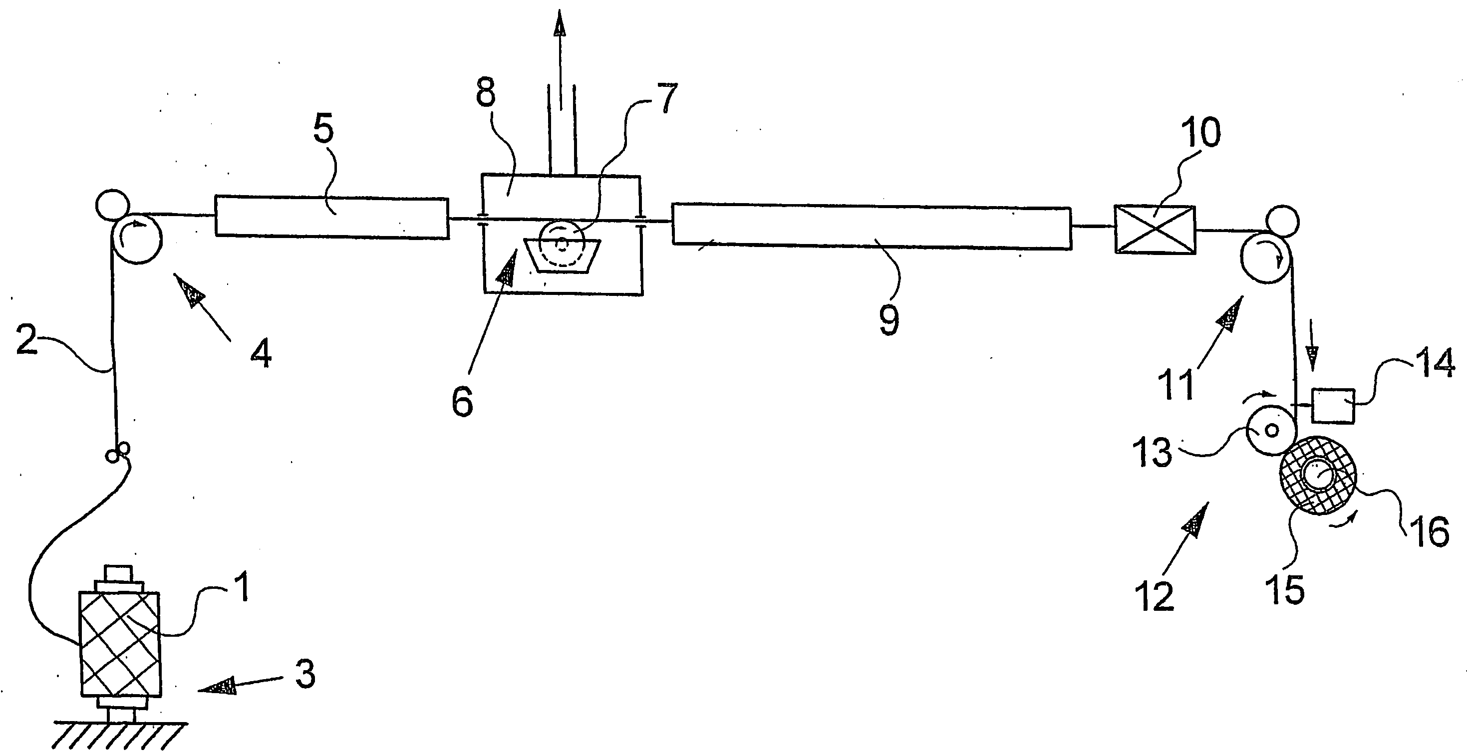
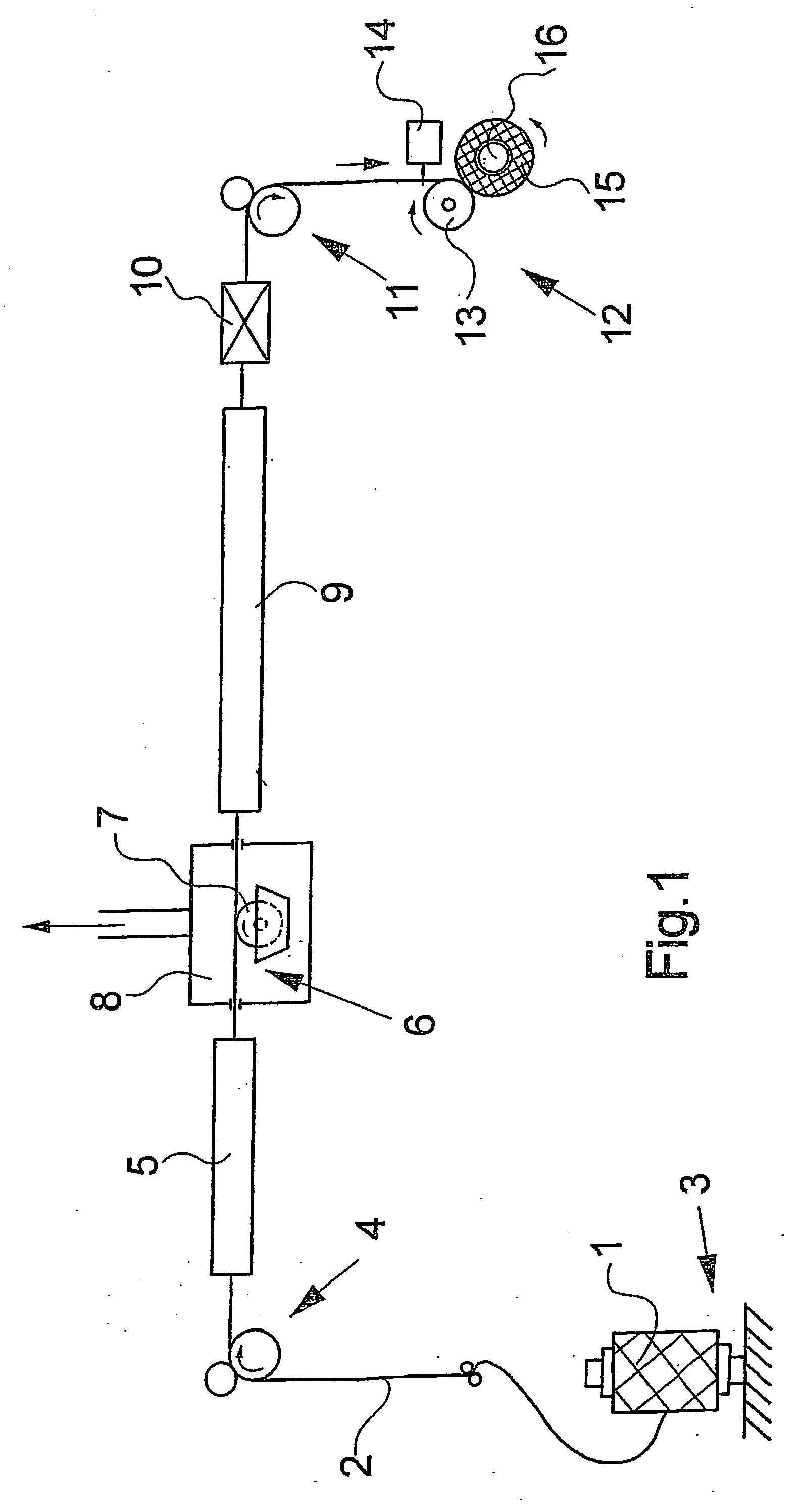
[0023]FIG. 1 schematically illustrates a processing station of a first embodiment of a texturing machine according to the invention. An illustration of the components of a machine frame for mounting the individual processing units has been omitted.

[0024] A creel frame 3 mounts a feed yarn package 1. The feed yarn package 1 holds a yarn 2, which is withdrawn from the feed yarn package 1 by a first feed system 4. Arranged in the path of the yarn downstream of the first feed system 4 are a heating device 5, a wetting device 6, a cooling device 9, a texturing unit 10, as well as a second feed system 11. From the second feed system 11, the yarn 2 advances to a takeup device 12, where the yarn 2 is wound to a package 15. The takeup device 12 comprises a drive roll 13, a yarn traversing device 14, and a package holder 16. The package 15 is driven by the drive roll 13 at a substantially constant peripheral speed.

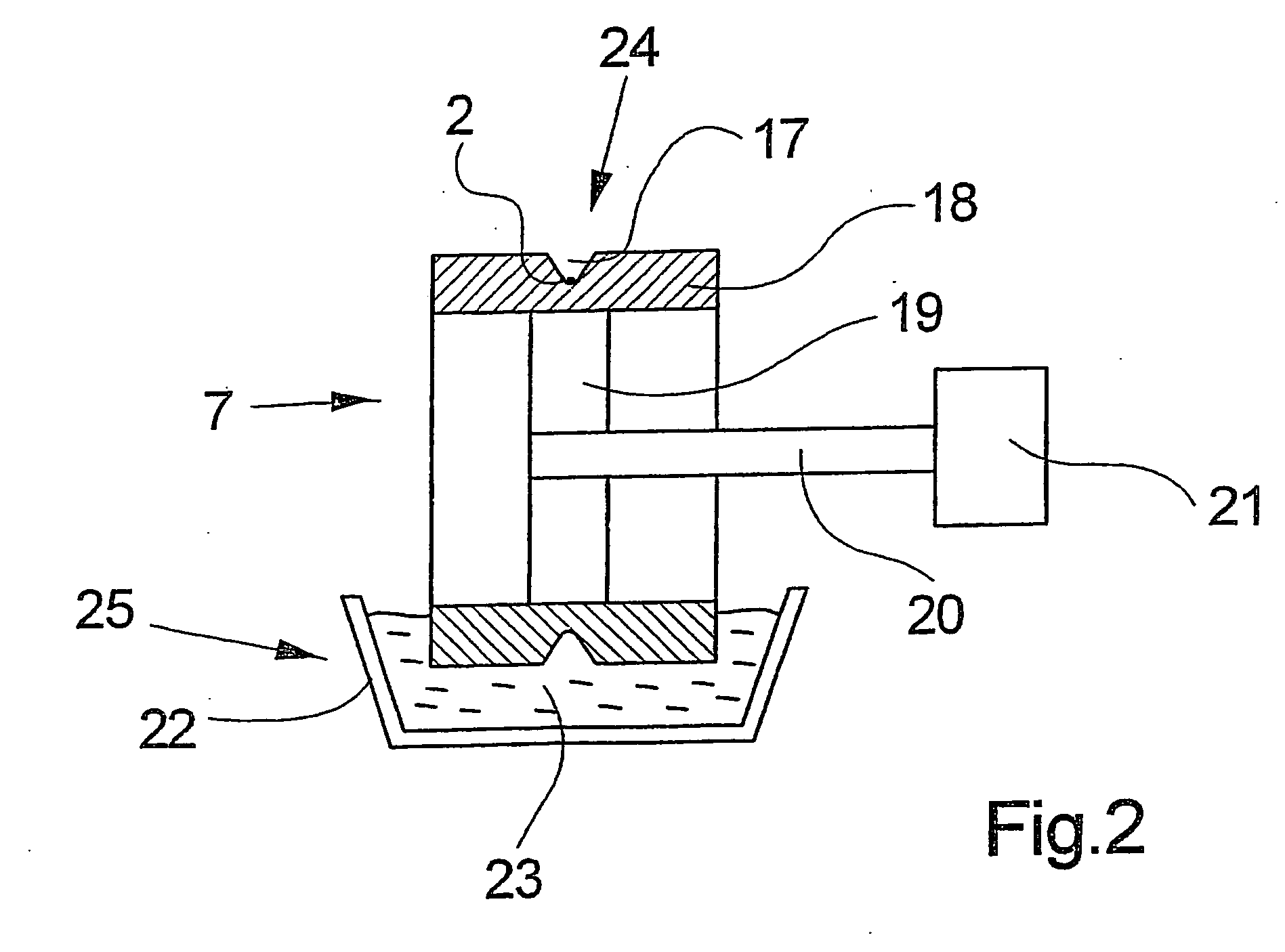
[0025] Within a texturing zone formed between the first feed system 4 and the...


PUM

PropertyMeasurementUnit
Speedaaaaaaaaaa
Circumferenceaaaaaaaaaa

Abstract

A texturing apparatus for draw texturing a synthetic yarn. To this end, the texturing machine comprises a first feed system, a heating device, a cooling device, a texturing unit, a second feed system, and a takeup device for winding the textured yarn. Between the heating device and the cooling device, a wetting device is provided for wetting the heated yarn with a cooling fluid for purposes of precooling. The wetting device consists of a rotatable cooling cylinder which includes on its circumference a yarn track that contains a cooling fluid. The yarn can be wetted by contacting the yarn track. At the point of contact, the yarn friction is advantageously dependent on the relative speed between the yarn and the yarn track on the circumference of the cooling cylinder.

Description

CROSS REFERENCE TO RELATED APPLICATION [0001] The present application is a continuation of international application PCT / EP03 / 04045, filed 17 Apr. 2003, and which designates the U.S. The disclosure of the referenced application is incorporated herein by reference.BACKGROUND OF THE INVENTION [0002] The invention relates to a texturing apparatus for draw texturing a synthetic multifilament yarn. A conventional texturing machine of this general type is disclosed, for example, in EP 0 879 907 A1 and corresponding U.S. Pat. No. 6,026,636. [0003] Texturing machines of this type are used for texturing one or more yarns, from a melt spun, flat yarn to produce a bulked and crimped yarn, which is suited for further processing to form a knit or woven fabric. To this end, the spun, flat yarn is withdrawn from a feed yarn package, textured and drawn within a texturing zone that includes a heating device, a cooling device, and a texturing unit, and wound to a package after having been textured. [...

Claims


Application Information

Patent Timeline
IPC IPC(8): D02G1/02D02J13/00
CPCD02J13/005D02G1/0266
Inventor PYRA, MICHAEL
Owner SAURER GMBH & CO KG
Why Eureka
Try Eureka