
Image forming device and color misregistration correction method for image forming device

a technology of image forming and image, which is applied in the field color misregistration correction methods of image forming devices, can solve the problems of color misregistration of multicolor images, uneven rotation, and deterioration of image quality, and achieve the effect of forming stably

Active Publication Date: 2005-03-03
SHARP KK
View PDF10 Cites 68 Cited by
  • Summary
  • Abstract
  • Description
  • Claims
  • Application Information

AI Technical Summary

Benefits of technology

[0021] The present invention was made to solve the foregoing problems. An object of the present invention is therefore to provide an image forming device and a color misregistration correction method, which allow for stably forming an excellent image with little color misregistration, by measuring the density of a pattern formed by superimposing (i) a pattern formed on a reference image supporting body and (ii) a pattern formed on another image supporting body, and controlling rotational phases of the image supporting bodies in accordance with the result of measurement.
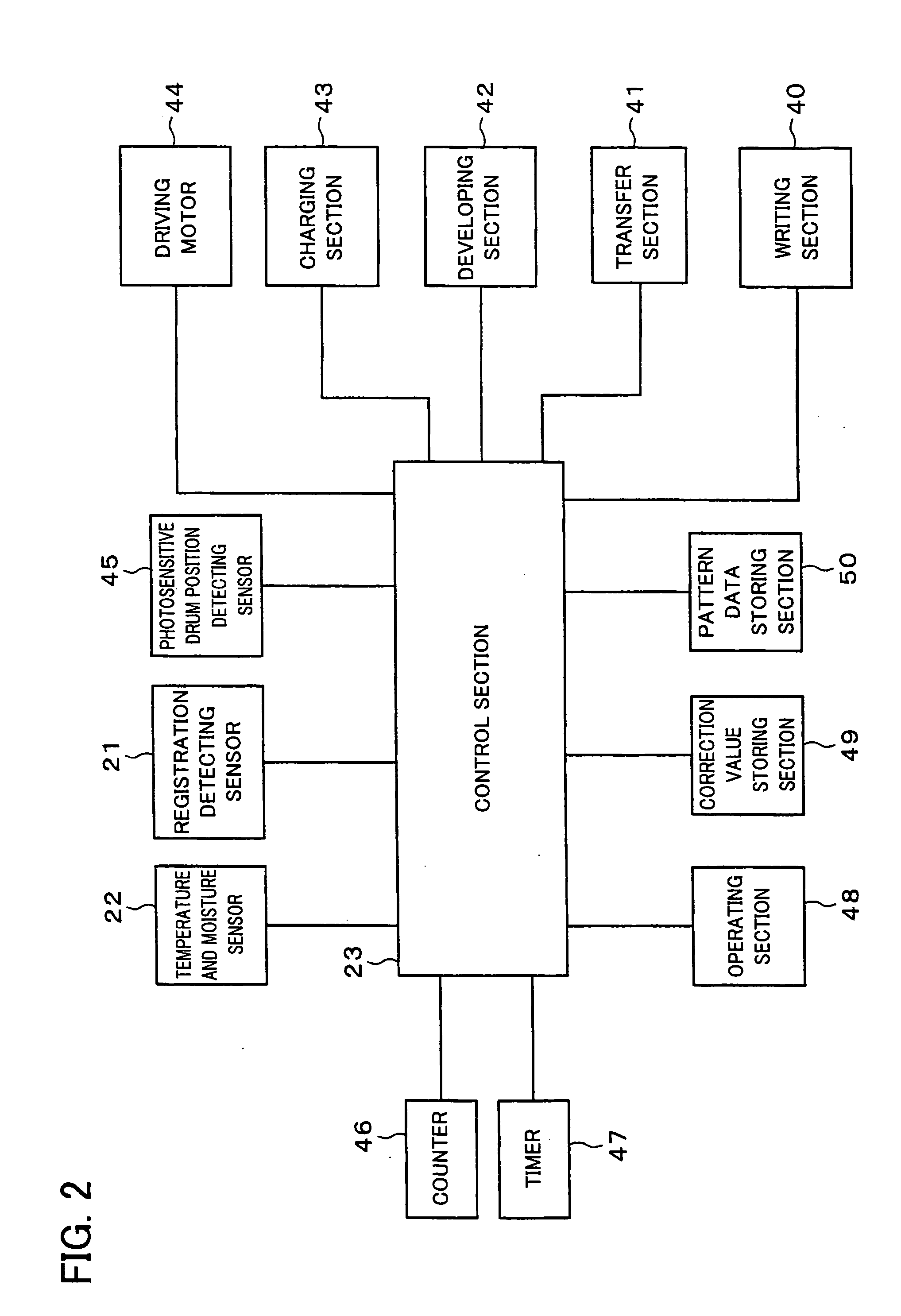
[0024] According to this arrangement, the density average value of each of the plurality of group images formed by superimposing the images of different color components is detected, and the correction value for synchronizing the rotational phases of the image supporting bodies is calculated in accordance with the density average value. By controlling the rotational phases of the image supporting bodies in accordance with the correction value, the rotational phases of the image supporting bodies can be synchronized. Therefore, it is possible to stably form an excellent image with little color misregistration.
[0025] Moreover, because the correction value is calculated by the image forming device itself, the correction value can be calculated more accurately, and the number of steps can be reduced, as compared with a case where the outputted image is visually checked by a human. Therefore, an accurate correction value can be calculated immdediately.

Problems solved by technology

With such image forming devices, the resultant multicolor images suffer from color misregistration if the images of the color components are not superimposed accurately.
This often deteriorates image quality.
Therefore, if the rotational axis (core) of the image supporting body is shifted, unevenness in rotation (a phenomenon that the surface velocity of the image supporting body is not constant) is caused.
In such a case, color misregistration is likely to occur due to the unevenness in rotation.
Thus, the color misregistration of multicolor images is a significant problem of the tandem-type image forming devices.
As a result, there is a problem that a computing unit or the like device is required.
Therefore, the detection is difficult in the case where the density variation within the pattern image formed by a single image supporting body is detected with respect to each image forming unit.
In addition, because the pattern image needs to be formed in each image forming unit, there is a problem that it is necessary to form pattern images respectively at four places corresponding to four colors (C, M, Y, and K).
Therefore, there is a problem that it is difficult to control the rotational phases at high accuracy.
Therefore, if there are phase differences among rotational movements of the image supporting bodies, there are problems that desired color misregistration correction cannot be performed, and / or that a long adjustment time is required due to errors occurring during adjustment.

Method used


Image

  • Image forming device and color misregistration correction method for image forming device
  • Image forming device and color misregistration correction method for image forming device
  • Image forming device and color misregistration correction method for image forming device

Examples


Embodiment Construction

[0040] With reference to FIGS. 1 to 13, the following describes one embodiment of the present invention.

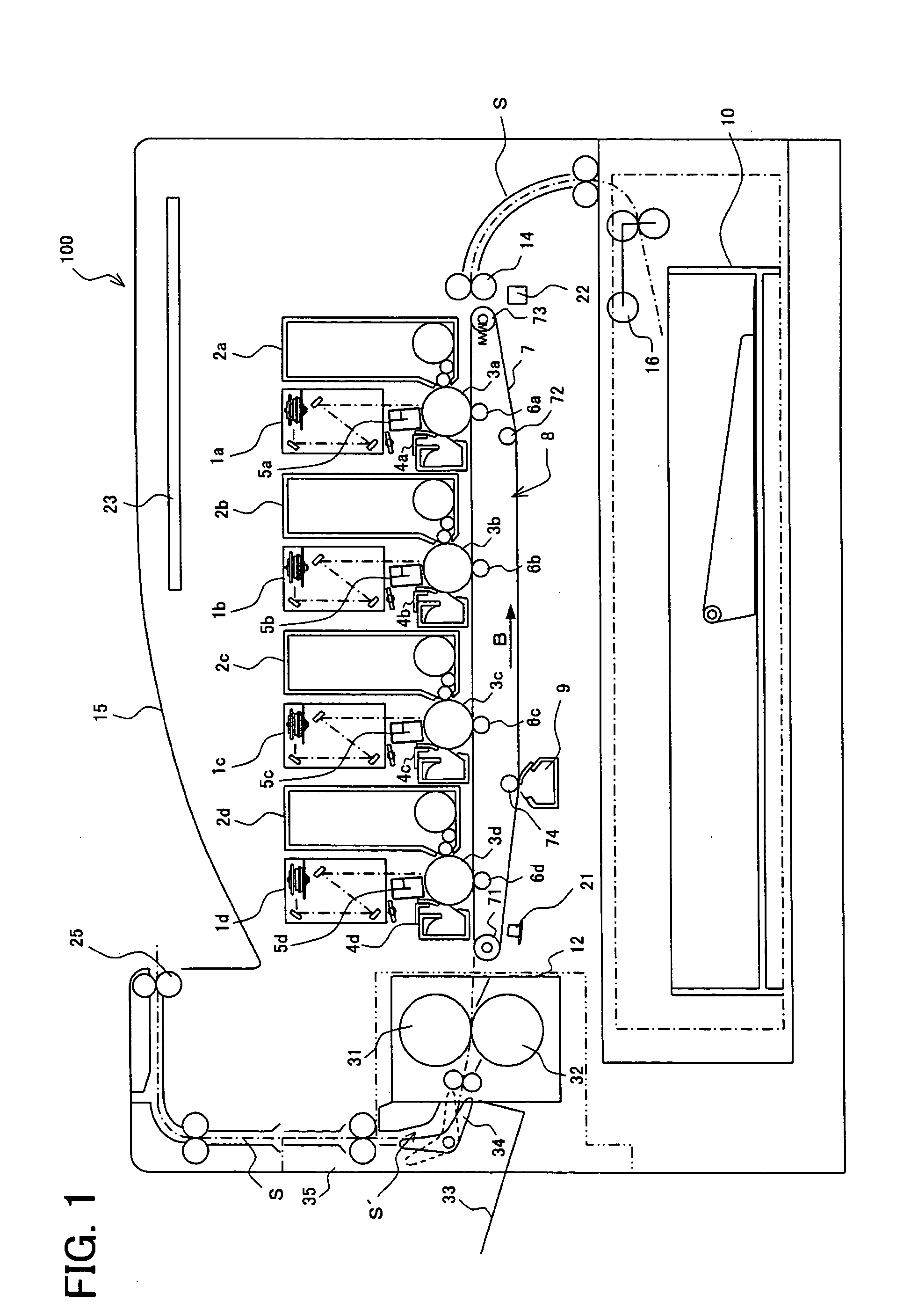
[0041]FIG. 1 is a cross-sectional view illustrating a schematic arrangement of an image forming device of the present embodiment.

[0042] An image forming device 100 of the present embodiment forms a multicolor image or a single-color image on a predetermined sheet (recording sheet), in accordance with image data inputted from an external entity. As shown in FIG. 1, the image forming device 100 includes a feed tray 10, ejection trays 15 and 33, and a fixing unit 12, in addition to members for controlling rotational phases of image supporting bodies so as to correct color misregistration of a multicolor image. The members for controlling the rotational phases of the image supporting bodies so as to correct the color misregistration of the multicolor image are described later.

[0043] The feed tray 10 is a tray for storing recording sheets on which images are to be recorded. The ejec...


PUM


Abstract

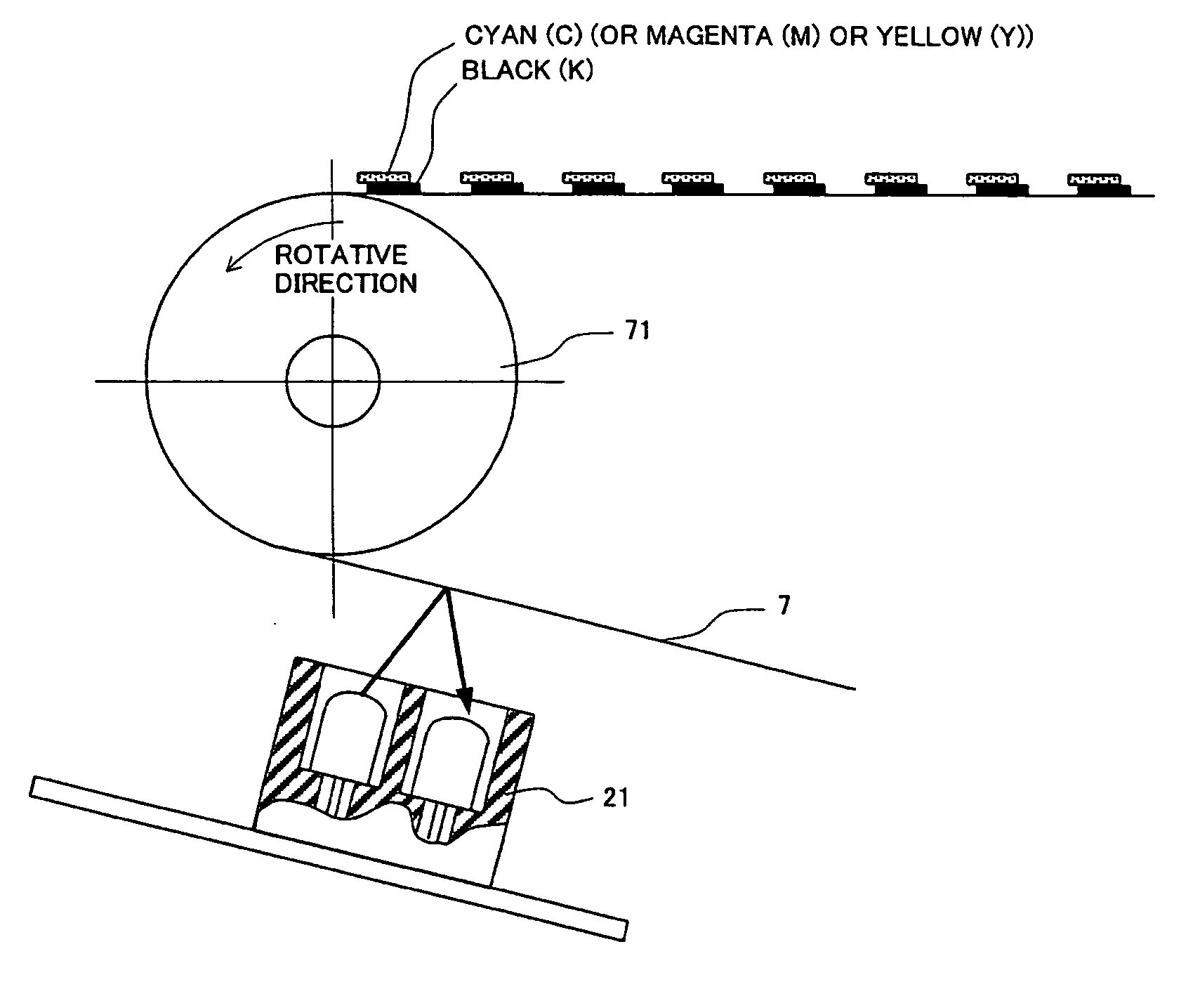
An image forming device and a color misregistration correction method allow for stable formation of excellent images with little color misregistration. A reference patch image is formed on a reference photosensitive drum 3, and transferred to a transfer belt 7. A correction patch image is formed on a correction-target photosensitive drum 3, and transferred onto the reference patch image by superimposition. A registration detecting sensor 21 detects a density average value of the reference patch image and the correction patch image. Based on the density average value, a correction value for controlling the correction-target photosensitive drum 3 is calculated, and rotational phase control is performed in accordance with the correction value.

Description

[0001] This nonprovisional application claims priority under 35 U.S.C. § 119(a) on patent application No. 2003 / 208888 filed in Japan on Aug. 26, 2003, the entire contents of which are hereby incorporated by reference. FIELD OF THE INVENTION [0002] The present invention relates to an electrophotographic image forming device and a color misregistration correction method for the image forming device. More specifically, the present invention relates to (i) an image forming device that automatically adjusts phases of unevenness in rotation of image supporting bodies (the unevenness in rotation of the image forming bodies results in a color misregistration of a multicolor image when the multicolor image is formed by superimposing color component images formed on the image supporting bodies or on a transfer supporting body), and relates to (ii) a color correction method for the image forming device, the method being for automatically correcting the color misregistration of the multicolor i...

Claims


Application Information

Patent Timeline
Patent Type & Authority Applications(United States)
IPC IPC(8): B41J2/44B41J2/45B41J2/455G03G15/00G03G15/01G03G21/14
CPCG03G15/0131G03G2215/00059G03G2215/0119G03G2215/0132G03G15/5058G03G2215/0158G03G2215/0164G03G15/0194G03G2215/0141
Inventor TOMITA, NORIOYAMAMOTO, MASANOBUTAKA, KYOSUKEHARADA, YOSHIKAZU
Owner SHARP KK
Learn More