Eureka AIR delivers breakthrough ideas for toughest innovation challenges, trusted by R&D personnel around the world.

System and method for selectively expanding or contracting a portion of a display using eye-gaze tracking

a technology of eye-gaze tracking and selective expansion, applied in the field of eye-gaze tracking systems and interactive graphical user interfaces, can solve problems such as display loss, and achieve the effect of reducing the loss of information or function, and increasing the ability to quickly acquire or click on target objects

Inactive Publication Date: 2005-03-03
IBM CORP
View PDF32 Cites 312 Cited by
  • Summary
  • Abstract
  • Description
  • Claims
  • Application Information

AI Technical Summary

Benefits of technology

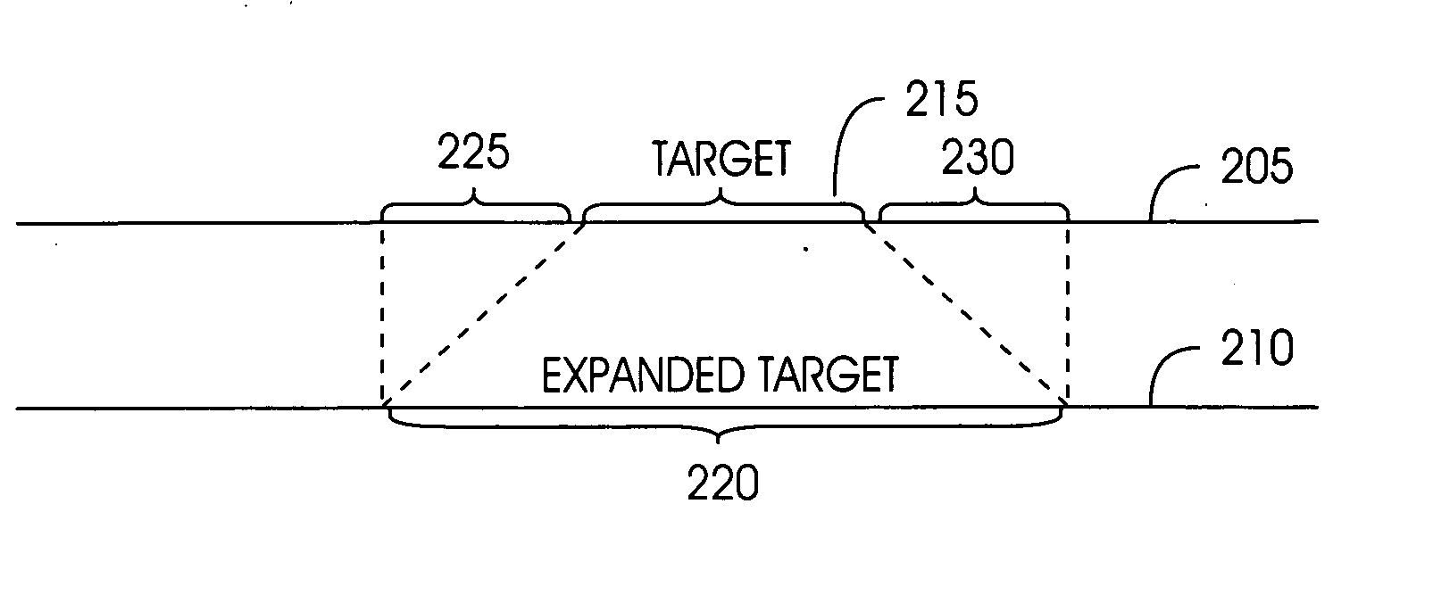
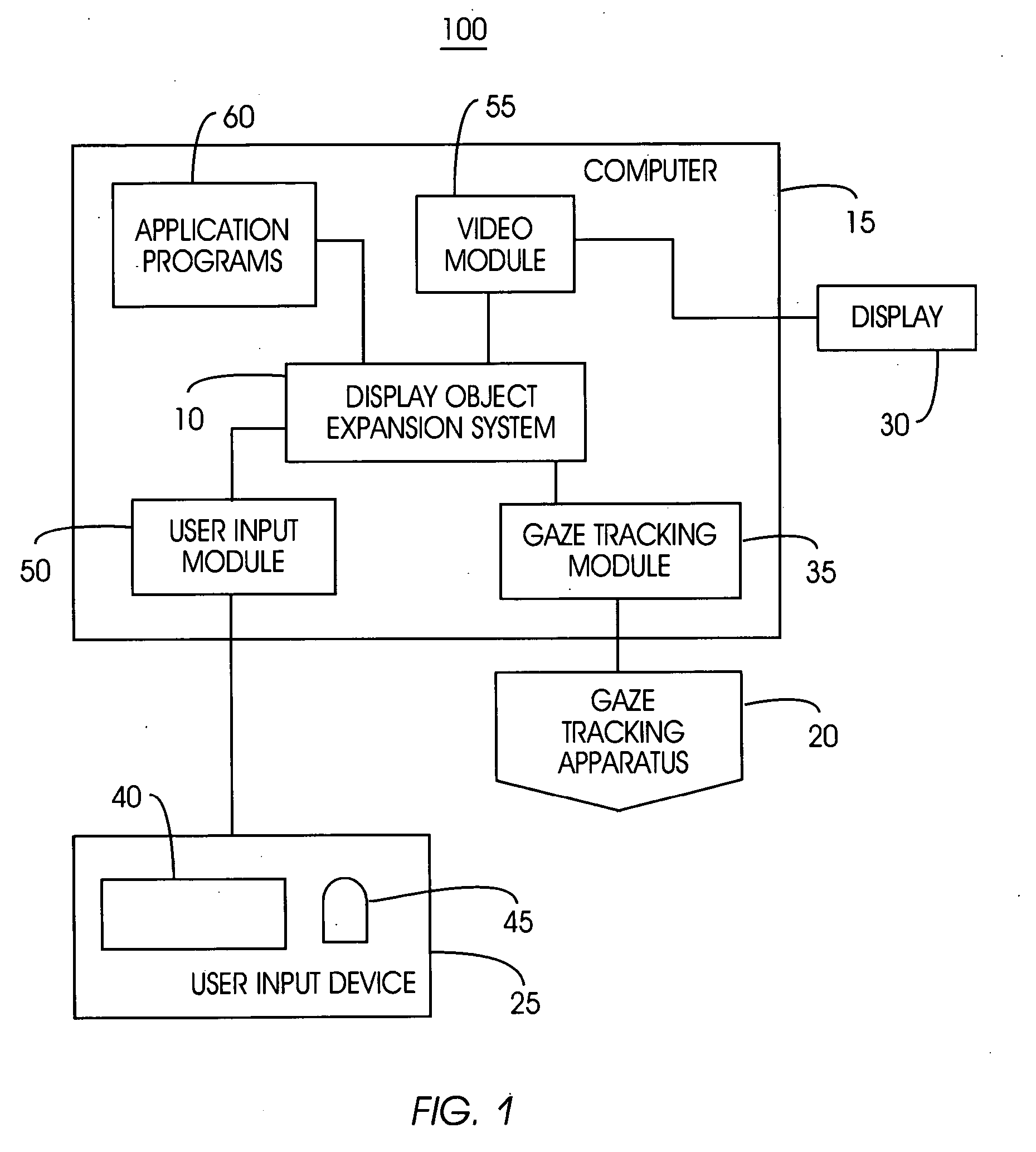
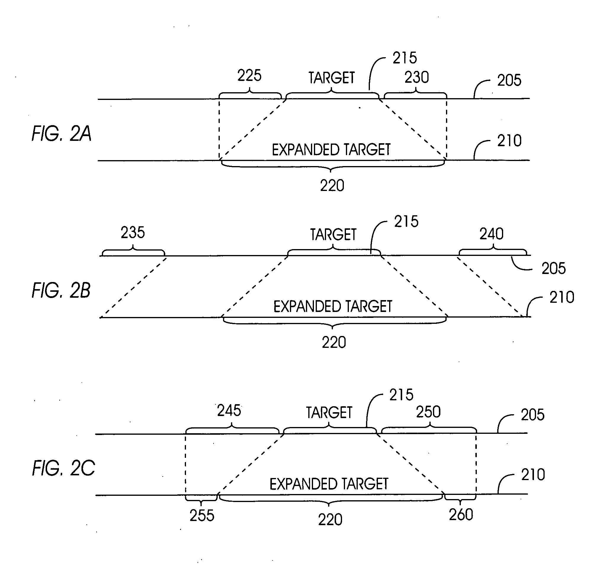
The present invention satisfies this need, and presents a system, a computer program product, and an associated method (collectively referred to herein as “the system” or “the present system”) for selectively expanding and / or contracting a portion of a display using eye-gaze tracking to increase the ability to quickly acquire or click on the target object. When an object in a display is expanded, some of the display is lost. The present system manages the screen display to accommodate that loss with minimum loss of information or function to the user.
When a user gazes at a graphical element such as a button, the present system changes the size of the actual button in the physical motor domain, making the button visually and physically larger. This object expansion is based on eye-gaze tracking. In contrast to conventional systems, the present system actually increases the size of the target instead of reducing the distance to the target.
When there are multiple adjacent targets below the gaze tracking resolution, the present system expands adjacent objects within the gaze spot and lets the user choose his or her intended target. The gaze spot is typically one visual degree in size. In comparison to the previous manual and gaze integrated pointing techniques (described for example is U.S. Pat. No. 6,204,828), the present invention may offer numerous advantages, among which are the following.
The prior method based on cursor warping could be disorienting because the cursor appears in a new location without continuity. The present system has continuous cursor movement similar to current display techniques. In addition, prior art methods based on cursor warping are based on the use of a mouse cursor. Consequently, the prior approach does not work on touch screen computers (such as a Tablet computer) where pointing is accomplished by a finger or a stylus, though certain types of touch screens could detect the finger or stylus position before touching the screen, enabling the present system to detect the user's intention of target selection.
The present system checks the eye-gaze position and expands the likely target. Because target expansion can be beneficial even if it occurs rather late in the process of a pointing trial, its requirement of eye-tracking system speed could be lower than a cursor warping pointing method. The latter method requires the tracking effect to be almost instantaneous. Furthermore, it is possible to simultaneously warp the cursor and expand the target, increasing speed of target acquisition even more.
The present system is applicable to a wider variety of environments than prior systems that are depended on the ability to “warp” a pointer. In a touch screen or a tablet PC environment, or a small hand-held personal digital assistant (PDA), or any application where there is a touch screen with a stylus, the pointer cannot be warped because it is a physical object. The present system is based on physical movement as opposed to cursor or mouse pointer making it applicable to more devices and applications.

Problems solved by technology

When an object in a display is expanded, some of the display is lost.

Method used


Image

  • System and method for selectively expanding or contracting a portion of a display using eye-gaze tracking
  • System and method for selectively expanding or contracting a portion of a display using eye-gaze tracking
  • System and method for selectively expanding or contracting a portion of a display using eye-gaze tracking

Examples


Embodiment Construction

The following definitions and explanations provide background information pertaining to the technical field of the present invention, and are intended to facilitate the understanding of the present invention without limiting its scope:

HTML document: A document marked up in HTML, a standard language for attaching presentation and linking attributes to informational content within documents.

Hyperlink: A link in an HTML document that leads to another web site, or another place within the same HTML document.

Interactive object: An object or element that accepts input from the user through typed commands, voice commands, mouse clicks, or other means of interfacing and performs an action or function as a result of the input.

Fixation: A gaze by a user's eye a particular point at a video screen.

Target: an interactive graphical element such as a button or a scroll bar hyperlink, or non-interactive object such as text which the user wishes to identify through a persistent stare.

We...


PUM


Abstract

A computer-driven system amplifies a target region based on integrating eye gaze and manual operator input, thus reducing pointing time and operator fatigue. A gaze tracking apparatus monitors operator eye orientation while the operator views a video screen. Concurrently, the computer monitors an input indicator for mechanical activation or activity by the operator. According to the operator's eye orientation, the computer calculates the operator's gaze position. Also computed is a gaze area, comprising a sub-region of the video screen that includes the gaze position. The system determines a region of the screen to expand within the current gaze area when mechanical activation of the operator input device is detected. The graphical components contained are expanded, while components immediately outside of this radius may be contracted and / or translated, in order to preserve visibility of all the graphical components at all times.

Description

FIELD OF THE INVENTION The present invention generally relates to gaze tracking systems and interactive graphical user interfaces. More particularly, the present invention relates to a system for selectively expanding and / or contracting portions of a video screen based on an eye-gaze, or combination of data from gaze tracking and manual user input. BACKGROUND OF THE INVENTION In human-computer interaction, one of the most basic elements involves selecting a target using a pointing device. Target selection is involved in opening a file with a mouse “click”, activating a world wide web link, selecting a menu item, redefining a typing or drawing insertion position, and other such operations. Engineers and scientists have developed many different approaches to target selection. One of the most popular target selection devices is the computer mouse. Although computer mice are practically essential with today's computers, intense use can be fatiguing and time consuming. Despite these l...

Claims


Application Information

Patent Timeline
IPC IPC(8): G06F3/01G06F3/048G06K9/00
CPCG06F3/013G06F2203/04806G06F3/0481G06F2203/0381
Inventor FARRELL, STEPHEN P.ZHAI, SHUMIN
Owner IBM CORP
Why Eureka
Eureka Blog
Learn More