
Bowler's Positive Control System And Method

a control system and positive technology, applied in the field of bowllers, can solve the problems of not being solved by any device, and the difficulty of giving the combined rotation to the ball in any consistent manner, and achieve the effect of positive control over the alignment of the ball

Inactive Publication Date: 2005-02-24
ROSENBLATT JOEL I
View PDF7 Cites 0 Cited by
  • Summary
  • Abstract
  • Description
  • Claims
  • Application Information

AI Technical Summary

Benefits of technology

[0003] Many students of the bowling art have recognized that the middle two fingers, which occupy adjacent holes in the ball, should be the source of the desired roll. These fingers should rotate the underside of the ball upward, an effect called lift as they leave the ball upon its release from the bowler's middle fingers. One or more of the bowler's middle fingers are used to lift the ball giving it this complex rotation about two axes and also to grip the ball with sufficient control at its delivery and release to prevent or reduce slippage and to enable the bowler to achieve lift with the most revolutions on the ball the bowler is capable of delivering, which is important to scattering the pins and achieving a strike. Attempts to achieve a better grip generally use a surface between the finger and the ball which increases the surface friction and the surface counter force to the force developed when lifting and releasing the ball in a direction to displace the finger placement relative to the ball. A device of this kind is shown in published patent application No. 20030045367, published Mar. 6, 2003, describing a polymeric material being substantially resilient and elastic which fits onto the finger end and with projections which may be hemispherical for contacting the surface of the ball. Depending upon the pressure exerted by the finger, the projections will flatten, forming a circular face onto the bowling ball and assisting in the bowler's grip of the bowling ball enabling the bowler to better initiate rotation as the bowling ball is released.
[0005] In an attempt to improve a bowler's control over the delivery of the ball, bowling ball finger hole inserts are used, for example as described in U.S. Pat. No. 4,892,308, of Gaunt, and the patents cited therein. Inserts, as shown and described in these patents, are used to better fit the finger hole to the bowler's finger or provide structural or dimensional changes into the finger hole to relieve stress on the finger and provide better ball control.
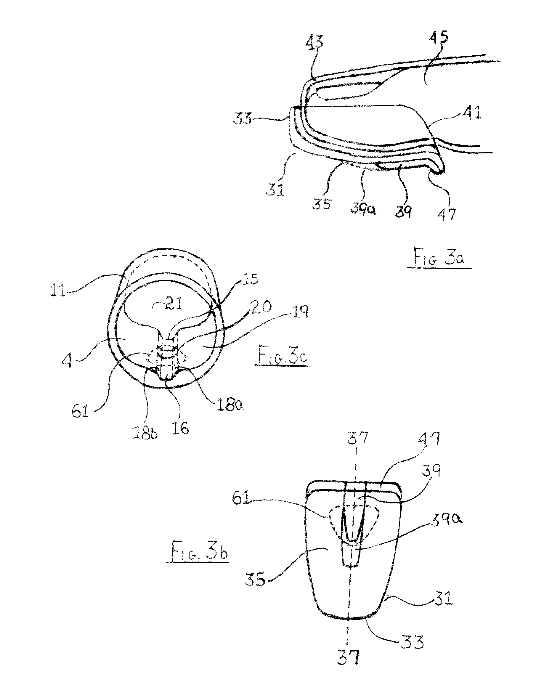
[0008] The mating interlocking opposed surfaces on the finger pad cover and the interior surface of the finger hole, or insert, may be arranged to provide a counter force to any movement of the finger pad cover relative to the bowling ball finger hole, in a direction at any angle to the direction in the release of the ball, for example as shown in preferred embodiment, at an angle to the primary axis along the finger pad or the matching primary axis of the finger hole or finger hole insert. Where, in a preferred embodiment for example, a counter force is established by mating surfaces on the finger pad cover and the finger hole interior surface that opposes relative displacement in the direction of the matching primary axis and primary axis or in the direction of the release of the ball from the finger pad cover, the bowler's delivery can be adjusted for any loss in kinetic energy caused by overcoming this counter force opposing release of the ball.
[0009] In a preferred embodiment, the use of the disclosed system of mating surfaces preventing a shift in relative displacement of the finger pad cover and the finger hole surface, gives the bowler a positive control over the alignment of the ball with the middle finger which is not available with a single gripping surface on the finger or in the finger hole, for example by an insert in the finger hole or by a gripping device on the finger of the bowler.
[0015] As would be understood by those skilled in the art, the interlocking surface may be in a finger hole insert or on the wall of the ball's finger hole, without departing from the principles of the invention. By primary axis and matching primary axis is meant an axis substantially aligned with the direction of the bowling ball at its release. However, as would be known to those skilled in the art, the interlocking three dimensional surfaces may be aligned at an angle with these axes to the extent the smooth separation of the ball from the finger at its release is not substantially impeded.

Problems solved by technology

Most bowlers experience great difficulty in giving this combined rotation to the ball in any consistent manner.
Solution of the problem faced by the bowler of establishing control and an means for developing a gripping force over the contact area made between the bowler's finger and the ball through the ball's finger hole, is not solved by any of the devices as now known or used.

Method used


Image

  • Bowler's Positive Control System And Method
  • Bowler's Positive Control System And Method
  • Bowler's Positive Control System And Method

Examples


Embodiment Construction

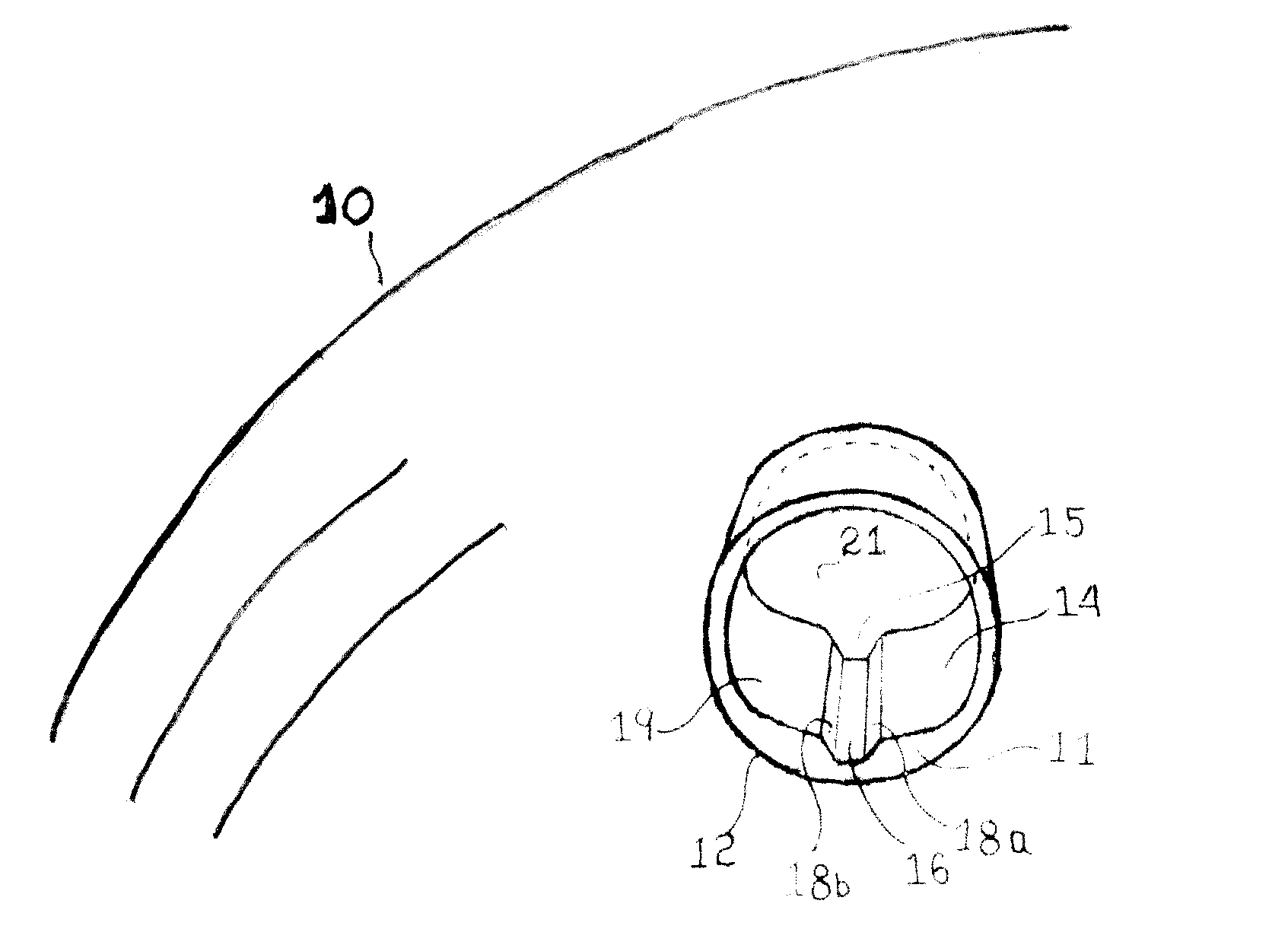
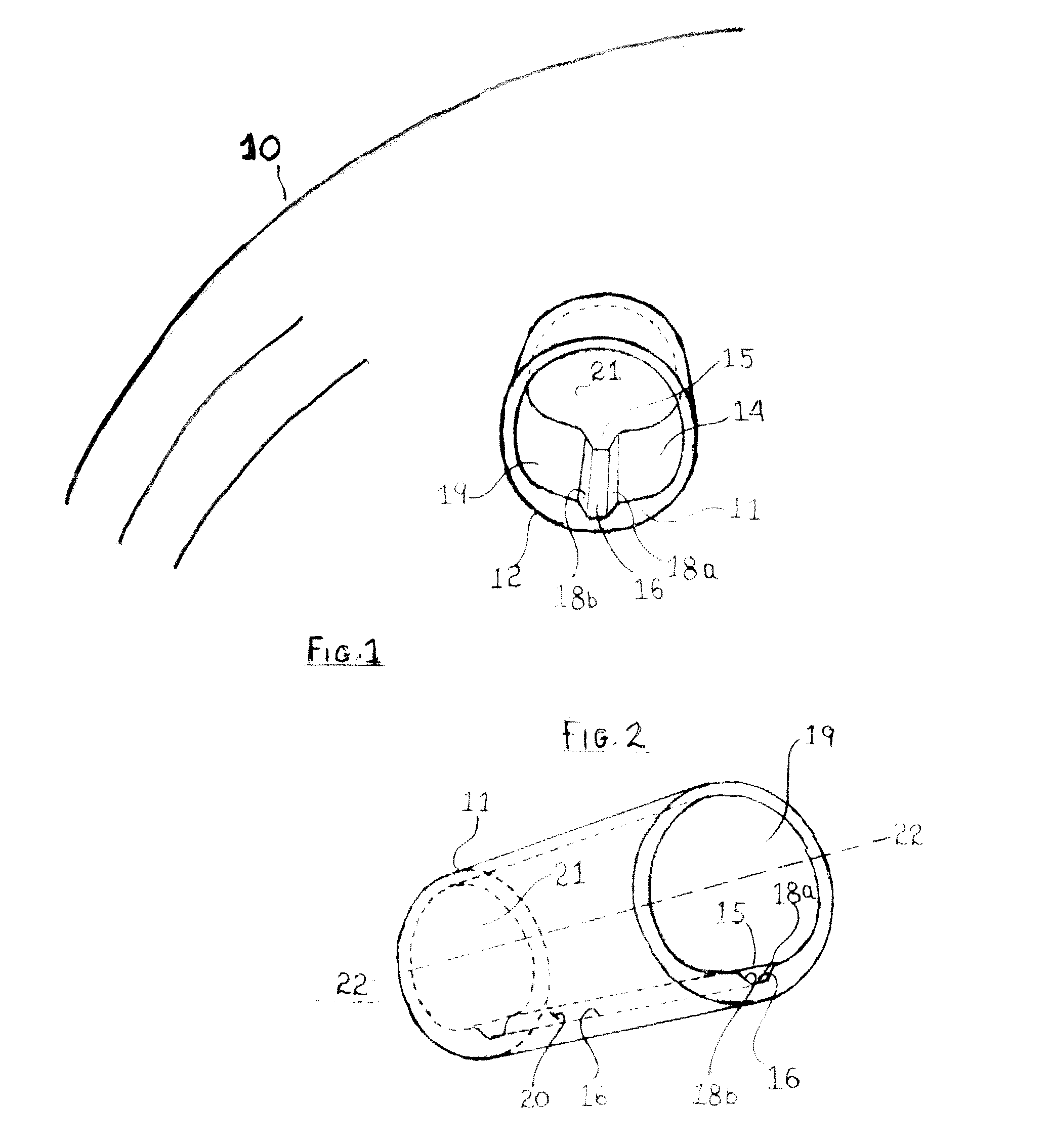
[0026] The invention as described by the disclosed inventive principles comprises matching or interlocking surfaces in the area of contact made by the interior surface of a bowling ball finger hole and finger pad cover mounted on a bowler's middle finger pad for achieving positive control when used in releasing the ball and imparting lift to the ball on its release.

[0027]FIG. 1 shows a bowling ball 10, in partial view, with a finger hole insert 11 when inserted into finger hole 12 and with the insert 11 shown partially in phantom. As would be understood by those skilled in the art, the disclosed invention and the inventive principles may be used in a preferred embodiment with a finger hole insert 11 or may be applied directly on the interior surface of the finger hole 12. The finger hole, or finger hole insert inner surface 14, as shown includes a three dimensional surface. shown generally by numeral 15 on insert inner surface 14, and with base 16 and side walls 18a and 18b, defini...


PUM


Abstract

A system including a finger pad with a three dimensional surface mates or interlocks with the surface of a bowling ball finger pad insert or the surface of a bowling ball finger hole, providing positive control over the alignment of the ball with the axis of the bowler's finger

Description

SUMMARY OF INVENTION [0001] A primary objective in bowling is a two rotary motions placed on the ball, called roll and spin, roll being the rotation of the ball in the direction of travel and spin being the rotation of the ball about an axis intersecting the roll axis and typically orthogonal to the roll axis. Most bowlers experience great difficulty in giving this combined rotation to the ball in any consistent manner. A description of one of many attempts to assist the bowler in imparting spin and roll are described in U.S. Pat. No. 4,371,163 of Shaffer. Described in that same U.S. Pat. No. 4,371,163, is the technique used by bowlers of using one or more middle fingers to deliver spin and roll to the ball in a process generally known as lift, or lifting the ball on its release from the bowler's hand. [0002] In lifting the ball on its release, the ball must be made to rotate in a forward direction, i.e., along an axis which is horizontal and perpendicular to the direction of motion...

Claims


Application Information

Patent Timeline
Patent Type & Authority Applications(United States)
IPC IPC(8): A63B37/00
CPCA63B37/0002
Inventor ADDINGTON, RANDALL A.ADDINGTON, W. ROBERTADDINGTON, W. ROBERT II
Owner ROSENBLATT JOEL I
Learn More